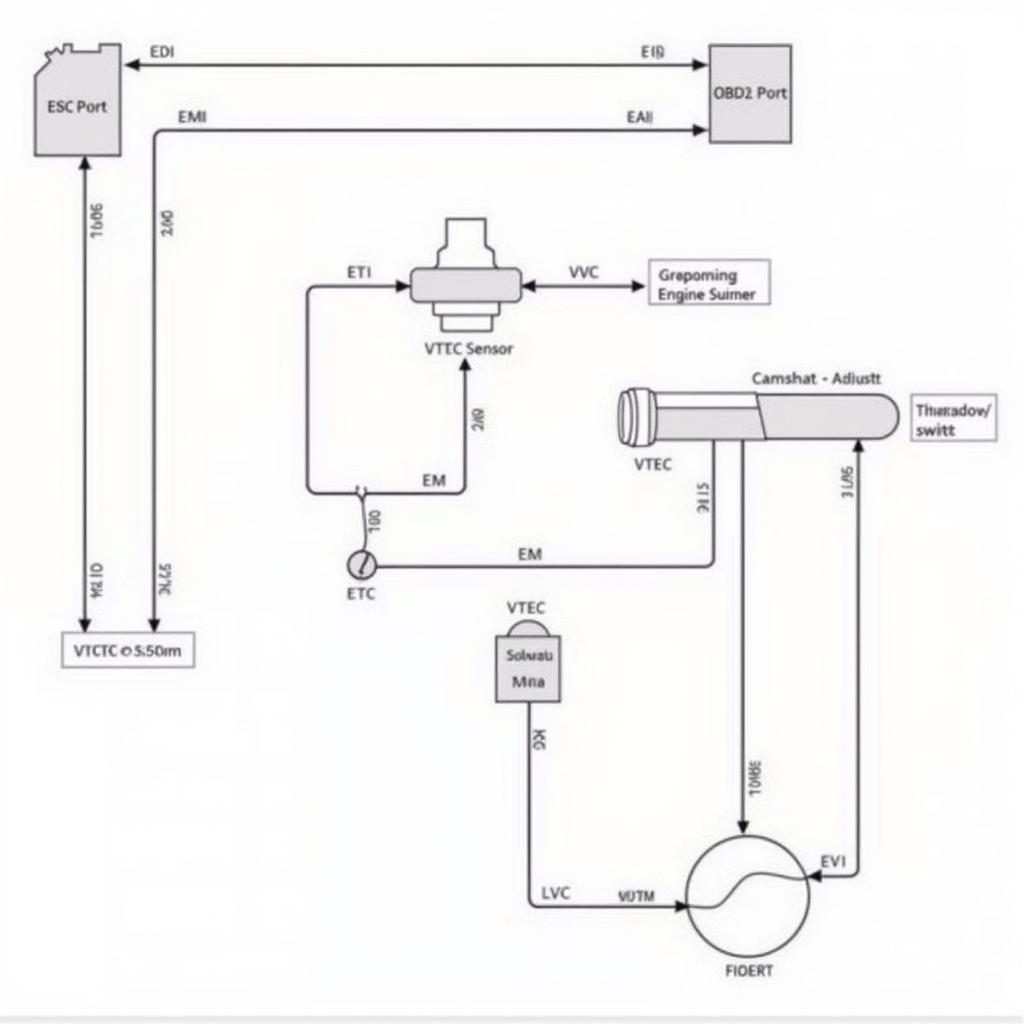
The OBD2 VTEC wiring diagram is like a roadmap for your car’s engine performance. It maps out the communication network between your car’s computer and the VTEC system, responsible for boosting power and efficiency. Whether you’re a seasoned mechanic or a car enthusiast, understanding this diagram can be key to diagnosing issues and unlocking your engine’s full potential.
What is VTEC and Why Should You Care?
VTEC, short for Variable Valve Timing and Lift Electronic Control, is a Honda innovation that revolutionized engine performance. In simple terms, VTEC allows your engine to breathe better at different speeds, delivering optimal power when you need it while maintaining fuel efficiency.
Think of it like this: Your engine has valves that control the flow of air and fuel. VTEC changes the timing and lift of these valves depending on your driving conditions. At lower RPMs, it prioritizes fuel economy. Step on the gas, and VTEC kicks in, unleashing more power by allowing more air and fuel into the engine.
Decoding the OBD2 VTEC Wiring Diagram
Now, let’s unravel the mystery of the OBD2 VTEC wiring diagram. This diagram shows you:
- The brains: The Engine Control Unit (ECU) is the control center, constantly receiving data from various sensors.
- The muscle: The VTEC solenoid is responsible for engaging and disengaging the VTEC system based on the ECU’s instructions.
- The messengers: Wires act as communication lines, transmitting signals between the ECU, sensors, and solenoid.
Common Issues and How the Diagram Helps
The OBD2 VTEC wiring diagram is particularly helpful in diagnosing problems related to:
- VTEC not engaging: This could be due to a faulty solenoid, wiring issues, or a malfunctioning sensor.
- Check Engine Light related to VTEC: The diagram can guide you to the specific area causing the error code.
- Performance issues: If you notice a lag in power delivery, the diagram can help pinpoint the source of the problem within the VTEC system.
By tracing the wires and connections, you can identify potential breaks, shorts, or loose connections that may be causing your VTEC system to misbehave.
Beyond Diagnostics: The Power of Knowledge
While the OBD2 VTEC wiring diagram is a valuable tool for troubleshooting, its true power lies in the knowledge it empowers you with. By understanding how the system works, you can:
- Better communicate with mechanics: Clearly explain the symptoms you’re experiencing and understand the repairs being proposed.
- Take on DIY projects: Confidently tackle minor repairs or modifications related to your VTEC system.
- Make informed decisions about your car’s maintenance: Recognize potential issues early on and address them proactively.
Unlocking Your Engine’s Potential
The OBD2 VTEC wiring diagram, far from being just a technical schematic, is your gateway to unlocking your engine’s true potential. By understanding its intricacies, you gain the knowledge to diagnose issues, optimize performance, and ensure the longevity of your engine. So, whether you’re a seasoned mechanic or a passionate car owner, take the time to study this diagram – your engine will thank you for it!


