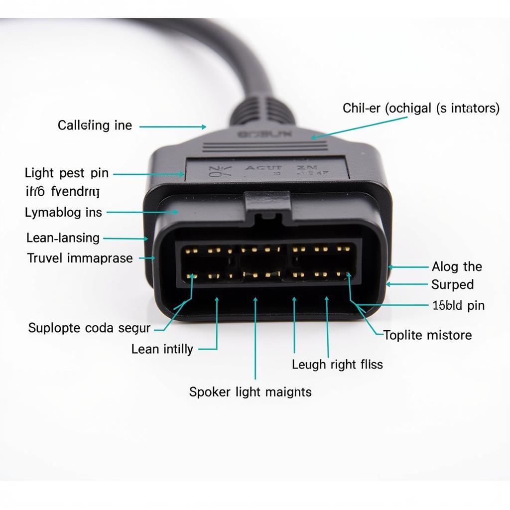
The OBD2 plug wiring diagram acts as the Rosetta Stone for your car’s computer system. It’s a map detailing how your vehicle’s onboard diagnostics system (OBD2) communicates with various sensors and modules, allowing you to diagnose and troubleshoot issues effectively.
Understanding the OBD2 plug wiring diagram can be immensely helpful for car enthusiasts, DIY mechanics, and even everyday drivers. It provides a clear picture of your vehicle’s internal communication network, enabling you to pinpoint the source of a problem before it escalates.
Decoding the OBD2 Plug Wiring Diagram
An OBD2 plug typically consists of 16 pins, each with a specific function. While the arrangement might vary slightly depending on the vehicle make and model, the core functions remain relatively consistent.
Here’s a general overview of the OBD2 pinout:
- Pin 1: Manufacturer Discretionary – This pin can be customized by the manufacturer for specific communication protocols.
- Pin 2: J1850 Bus+ (Ford & Chrysler) – Used for data transmission in vehicles from Ford and Chrysler.
- Pin 3: Manufacturer Discretionary
- Pin 4: Chassis Ground
- Pin 5: Signal Ground
- Pin 6: CAN High (J-2284) – Part of the Controller Area Network (CAN) bus system used in most modern vehicles for high-speed data communication.
- Pin 7: ISO 9141-2 K-Line – Primarily used in European and Asian vehicles for diagnostics.
- Pin 8: Battery Power
- Pin 9: Manufacturer Discretionary
- Pin 10: J1850 Bus- (Ford & Chrysler) – Complements Pin 2 for bidirectional data exchange.
- Pin 11: Manufacturer Discretionary
- Pin 12: Manufacturer Discretionary
- Pin 13: Manufacturer Discretionary
- Pin 14: CAN Low (J-2284) – Complements Pin 6 for balanced data transmission within the CAN bus system.
- Pin 15: ISO 9141-2 L-Line – Works in conjunction with Pin 7 for diagnostics.
- Pin 16: Battery Positive
“Having a firm grasp of the OBD2 pinout is akin to knowing the language your car speaks,” says automotive electronics expert, Dr. Emily Carter. “It allows you to directly communicate with your vehicle’s systems, unlocking a wealth of information about its health and performance.”
Utilizing the OBD2 Plug Wiring Diagram for Diagnostics
The OBD2 plug wiring diagram is essential for identifying the communication protocols used by your vehicle. This information is crucial for selecting the correct OBD2 scanner and interpreting the data it retrieves.
For instance, if your car uses the CAN bus system, you’ll need an OBD2 scanner compatible with CAN protocols. Similarly, understanding the specific pins assigned for communication (like Pins 2, 6, 7, 10, 14, and 15) can help troubleshoot connectivity issues.
Furthermore, knowing the function of each pin can aid in advanced diagnostics. For example, you can use a multimeter to test for voltage at specific pins to check for wiring faults or sensor malfunctions.
Common Applications of OBD2 Plug Wiring Diagrams
Knowing how to read an OBD2 plug wiring diagram opens up a range of possibilities for vehicle diagnostics and customization:
-
Troubleshooting Engine Issues: By connecting an OBD2 scanner, you can retrieve diagnostic trouble codes (DTCs) that pinpoint engine problems such as misfires, oxygen sensor malfunctions, or emissions system issues.
-
Monitoring Vehicle Performance: The diagram helps you understand which sensors provide data on parameters like speed, RPM, fuel economy, and engine load, allowing you to monitor your vehicle’s performance and identify potential issues.
-
Custom Installations: For car enthusiasts and DIY mechanics, the OBD2 plug wiring diagram is crucial for integrating aftermarket devices such as performance chips, gauges, or alarm systems.
-
Advanced Diagnostics: Mechanics use the diagram alongside professional-grade scan tools to perform in-depth diagnostics, including live data monitoring, actuator tests, and system resets.
Conclusion
The OBD2 plug wiring diagram is an indispensable tool for anyone looking to delve deeper into their vehicle’s inner workings. It provides a roadmap for understanding how your car’s computer system communicates, allowing you to diagnose issues, monitor performance, and even customize your ride. By familiarizing yourself with this diagram, you gain valuable insights into the health and functionality of your vehicle, empowering you to make informed decisions about its maintenance and upkeep.
FAQs
-
Can I use any OBD2 scanner with my car? Not necessarily. Ensure your scanner is compatible with your car’s communication protocols (e.g., CAN, J1850).
-
Where can I find the OBD2 plug wiring diagram for my specific car? Service manuals, online forums, and manufacturer websites are good places to start.
-
Is it safe to probe the OBD2 plug pins with a multimeter? Yes, but exercise caution and consult a manual to avoid short-circuiting any components.
Need More Help?
For any further assistance or queries, don’t hesitate to contact our expert team via WhatsApp: +1(641)206-8880, Email: [email protected]. We offer 24/7 customer support to help you navigate the world of OBD2 diagnostics.


