The OBD2 port, often located under the driver’s side dashboard, is a critical component for diagnosing car problems. At its heart lies the OBD2 pins diagram, a 16-pin connector that acts as the communication gateway between your car’s computer and diagnostic tools like OBD2 scanners. This article delves into the intricacies of the OBD2 pins diagram, empowering you to understand the language of your car.
Deciphering the OBD2 Pins Diagram
The OBD2 standard designates specific functions to each pin, ensuring uniformity across different car makes and models. This standardized layout allows mechanics and car enthusiasts alike to quickly access vital vehicle data.
Pin 1 & 2: Reserved for Manufacturer Use
While most pins adhere to a universal standard, pins 1 and 2 are reserved for manufacturer-specific protocols. This customization allows manufacturers to incorporate diagnostic features tailored to their vehicles.
Pin 3: Communicating with the Engine Control Unit (ECU)
Pin 3 is the communication line for the SAE J1850 PWM protocol, primarily used by Ford vehicles. It enables the transmission of data between the OBD2 scanner and the ECU, the brain behind your car’s engine management.
Pin 4: Chassis Control and More
Pin 4 plays a crucial role in accessing chassis control modules, responsible for functions like anti-lock brakes (ABS) and electronic stability control (ESC). Additionally, it serves as the ground for pin 5, ensuring proper voltage levels for communication.
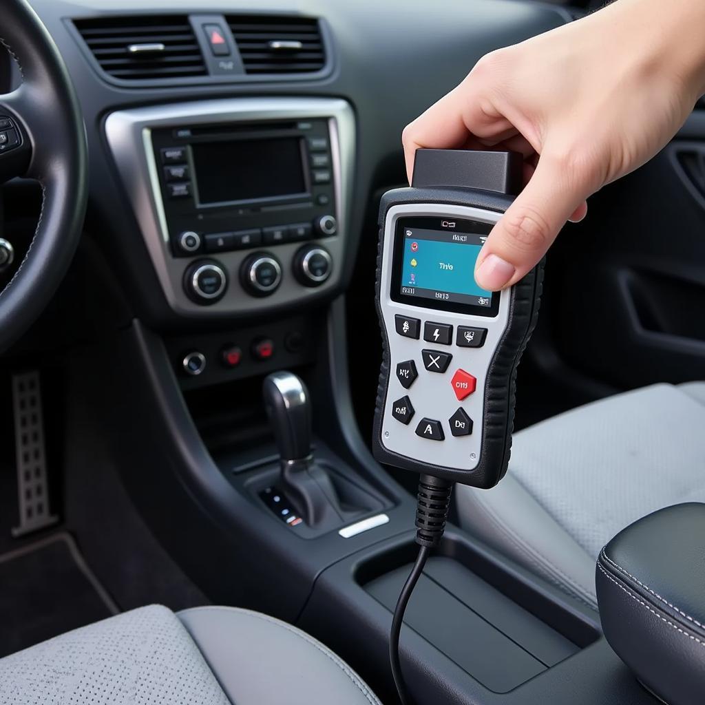
 OBD2 Scanner Connected to a Car's OBD2 Port
Pin 5: Grounding the Connection
Pin 5 is the signal ground, providing a common reference point for voltage measurements. This grounding mechanism ensures accurate data transmission and prevents electrical interference.
Pin 6 & 14: CAN High & CAN Low (Controller Area Network)
Pins 6 and 14 form the backbone of modern car communication, utilizing the Controller Area Network (CAN) protocol. This high-speed network allows various modules within the vehicle to communicate efficiently.
Pin 7: ISO 9141-2 K-Line Communication
Pin 7 facilitates communication using the ISO 9141-2 protocol, commonly found in European and Asian vehicles. It’s another standard for transmitting data between the OBD2 scanner and the vehicle’s control modules.
[custom obd2 pid]
Pin 8 & 16: Powering the Scanner
Pin 16 provides the battery voltage (12V) directly from your car’s battery, supplying power to the OBD2 scanner. This eliminates the need for an external power source for the scanner. Pin 8, on the other hand, serves as a connection to the battery positive terminal but is not always used.
Pin 9 & 11: Reserved for Future Use
Looking ahead, pins 9 and 11 are reserved for future expansion of the OBD2 standard. This foresight allows for the integration of new technologies and diagnostic capabilities in the future.
Pin 10: SAE J1850 Bus+ Communication
Pin 10 is the communication line for the SAE J1850 VPW protocol, primarily employed by General Motors vehicles. It facilitates data transfer between the OBD2 scanner and the vehicle’s computer system.
Pin 12 & 13: ISO 9141-2 L-Line & Battery Power
Pin 12, similar to pin 7, supports the ISO 9141-2 protocol, but it’s specifically designated as the L-Line. Pin 13, like pin 16, provides battery power (12V), offering an alternative power source for the OBD2 scanner.
[obd2 civic 440cc injectors]
Importance of Understanding the OBD2 Pins Diagram
While you don’t need to memorize every pin’s function, a basic understanding of the OBD2 pins diagram empowers you to:
- Utilize advanced diagnostic tools: Knowledge of the pins diagram allows you to use professional-grade OBD2 scanners with specialized functions.
- Troubleshoot specific systems: By understanding which pins correspond to different vehicle systems, you can target your diagnostic efforts more effectively.
- DIY car repairs: For the mechanically inclined, this knowledge can aid in performing basic car repairs and maintenance.
FAQs
Q1: Can I damage my car by connecting an OBD2 scanner incorrectly?
A: No, the OBD2 port and its pins are designed to prevent damage from incorrect connections. However, it’s always best to consult your vehicle’s owner’s manual for proper usage.
Q2: Are all OBD2 scanners compatible with all car makes and models?
A: While the OBD2 standard promotes compatibility, certain scanners may offer advanced features specific to certain car manufacturers. It’s crucial to choose a scanner that supports your vehicle’s make and model.
Q3: What are the common uses of an OBD2 scanner?
A: OBD2 scanners are commonly used to read and clear diagnostic trouble codes (DTCs), monitor engine performance data, and reset service lights.
Q4: Is it legal to use an OBD2 scanner on my own car?
A: Yes, it is legal to use an OBD2 scanner on your own vehicle for diagnostic and maintenance purposes.
[obd2 port gauge display]
Conclusion
Understanding the OBD2 pins diagram unlocks a deeper level of communication with your car. By comprehending the functions of these pins, you gain valuable insights into your vehicle’s inner workings, enabling you to diagnose issues effectively, utilize advanced diagnostic tools, and potentially save on costly repairs. Equip yourself with this knowledge and embark on a journey of informed car ownership.
Need assistance with your car’s diagnostics or looking for expert advice? Contact our team via WhatsApp at +1(641)206-8880 or email us at [email protected]. Our 24/7 customer support team is here to assist you every step of the way.

