The OBD2 port, a 16-pin connector typically found under the driver’s side dashboard, has revolutionized vehicle diagnostics. But have you ever wondered about the intricate network behind that seemingly simple interface – the OBD2 port wiring? This comprehensive guide delves into the complexities of the OBD2 port wiring, empowering you with the knowledge to understand its functions and even troubleshoot potential issues.
Unraveling the OBD2 Port Wiring Scheme
The OBD2 standard, while ensuring uniformity across vehicle makes and models, employs a standardized wiring configuration for its 16 pins. Each pin serves a specific function, categorized as follows:
- Power Supply: Pin 16 provides a constant 12V supply, essential for powering your OBD2 scanner.
- Ground Connections: Pins 4 and 5 act as ground connections, completing the electrical circuit.
- Communication Lines: Pins 2, 6, 7, 10, 14, and 15 are dedicated to communication protocols like J1850 PWM, J1850 VPW, ISO 9141-2, and CAN bus. These lines enable the transmission of diagnostic data between your vehicle’s ECU and the OBD2 scanner.
- Manufacturer-Specific Pins: Pins 1, 3, 8, 9, 11, and 12 offer flexibility for manufacturers to incorporate functionalities specific to their vehicles. These functions might include manufacturer-specific diagnostic modes or communication protocols.
Deciphering the Language of Your OBD2 Port Wiring
Understanding the purpose of each pin is crucial for effective vehicle diagnostics. Here’s a breakdown of the functions associated with each pin:
- Manufacturer Discretionary: Reserved for manufacturer-specific use.
- J1850 Bus+: Used for communication in vehicles employing the J1850 PWM protocol.
- Manufacturer Discretionary: Reserved for manufacturer-specific use.
- Chassis Ground: Provides a ground connection for various vehicle systems.
- Signal Ground: Serves as a reference ground for sensors and signals.
- CAN High (CAN-H): Carries the high signal level for the CAN bus communication protocol.
- ISO 9141-2 K-Line: Used for communication in vehicles following the ISO 9141-2 protocol.
- Manufacturer Discretionary: Reserved for manufacturer-specific use.
- Manufacturer Discretionary: Reserved for manufacturer-specific use.
- J1850 Bus-: Complements Pin 2 for communication in vehicles using the J1850 PWM protocol.
- Manufacturer Discretionary: Reserved for manufacturer-specific use.
- Manufacturer Discretionary: Reserved for manufacturer-specific use.
- Manufacturer Discretionary: Reserved for manufacturer-specific use.
- CAN Low (CAN-L): Complements Pin 6 for the CAN bus communication protocol, carrying the low signal level.
- ISO 9141-2 L-Line: Works in conjunction with Pin 7 for the ISO 9141-2 communication protocol.
- Battery Voltage: Supplies a constant 12V power source from the vehicle’s battery.
Common OBD2 Port Wiring Issues and How to Troubleshoot Them
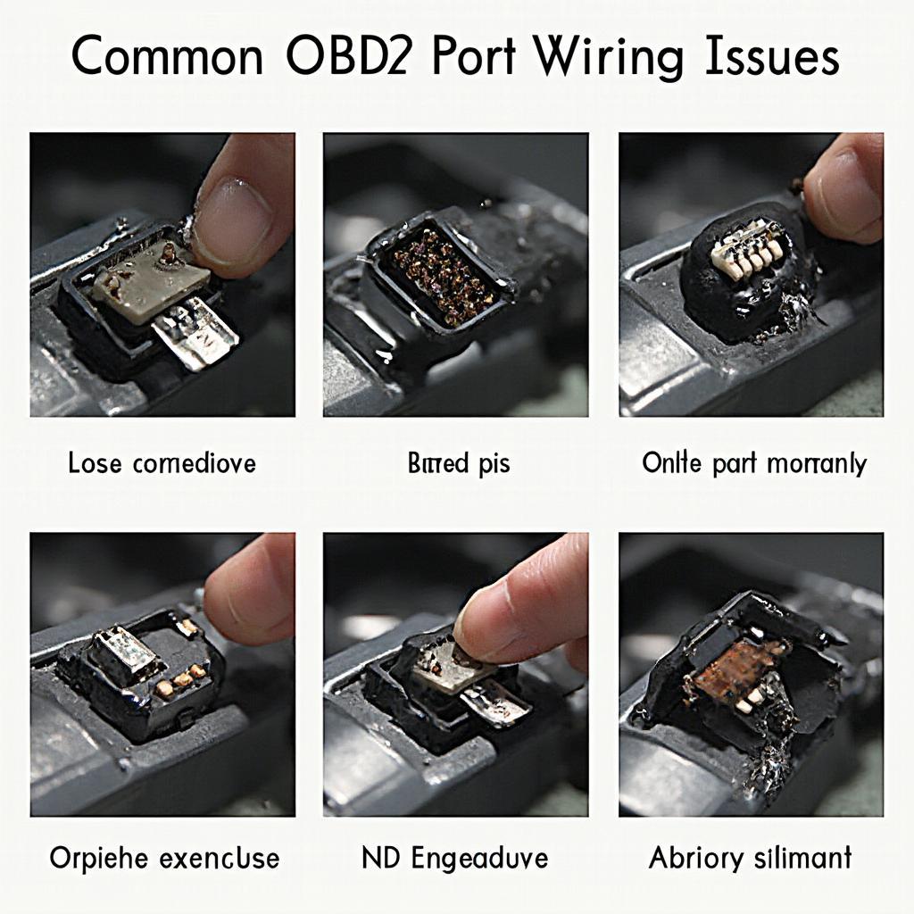
 Common OBD2 Port Wiring Issues
While the OBD2 port is a robust system, you might encounter issues due to:
- Loose Connections: Ensure the connector is securely fastened to the port.
- Damaged Pins: Inspect the pins for bending or breakage, requiring repair or replacement if necessary.
- Corrosion: Clean any corrosion on the pins or within the port using a specialized electrical contact cleaner.
- Blown Fuses: Check the fuses related to the OBD2 port and replace any blown fuses.
If these troubleshooting steps don’t resolve the issue, it’s advisable to consult a qualified automotive electrician for further diagnosis and repair.
Beyond the Basics: Advanced Insights into OBD2 Port Wiring
For those seeking a deeper understanding, the OBD2 port wiring unveils a world of possibilities:
- Vehicle-Specific Diagnostics: Manufacturer-specific pins offer access to advanced diagnostic modes tailored to your vehicle.
- Data Logging and Performance Monitoring: The communication lines can be utilized for real-time data logging, allowing you to monitor various vehicle parameters like engine speed, coolant temperature, and oxygen sensor readings.
- Custom Applications: With the right knowledge and tools, you can create custom applications to interact with your vehicle’s ECU via the OBD2 port, enabling possibilities like remote diagnostics and performance tuning.
Conclusion
Understanding the intricacies of OBD2 port wiring unlocks a wealth of information about your vehicle’s health and performance. This knowledge empowers you to perform basic diagnostics, troubleshoot common issues, and even explore advanced applications. Remember, while this guide provides a comprehensive overview, always refer to your vehicle’s specific wiring diagram and consult a qualified professional when dealing with complex electrical systems.
FAQ
Q1: Can I damage my car by tampering with the OBD2 port wiring?
A1: While the OBD2 port is designed to be relatively safe, it’s crucial to avoid probing the pins with sharp objects or applying excessive force, as this can damage the port or the connected circuitry. Always exercise caution and consult a professional if unsure.
Q2: My OBD2 scanner isn’t powering on. What could be the problem?
A2: If your OBD2 scanner isn’t receiving power, the issue might lie with the vehicle’s fuse box. Check the fuse associated with the OBD2 port or cigarette lighter, as they often share a fuse.
Q3: Why is my OBD2 scanner not communicating with my car?
A3: Communication issues can arise from various factors, including a blown fuse, a damaged OBD2 port, or incompatibility between the scanner and your vehicle’s communication protocol.
For any assistance or inquiries, feel free to reach out to our expert team via WhatsApp: +1(641)206-8880, Email: [email protected]. We’re available 24/7 to address your concerns.

