A color OBD2 wiring diagram is an essential tool for anyone working with a vehicle’s onboard diagnostics. It provides a visual representation of the wiring connections, making it easier to troubleshoot issues, install aftermarket devices, or simply understand how your car’s systems communicate. This guide will dive deep into the intricacies of OBD2 wiring diagrams, focusing on the importance of color codes and how to interpret them. After reading this article, you will be well equipped to tackle any OBD2 related project with confidence.
Decoding the OBD2 Connector: A Colorful Guide
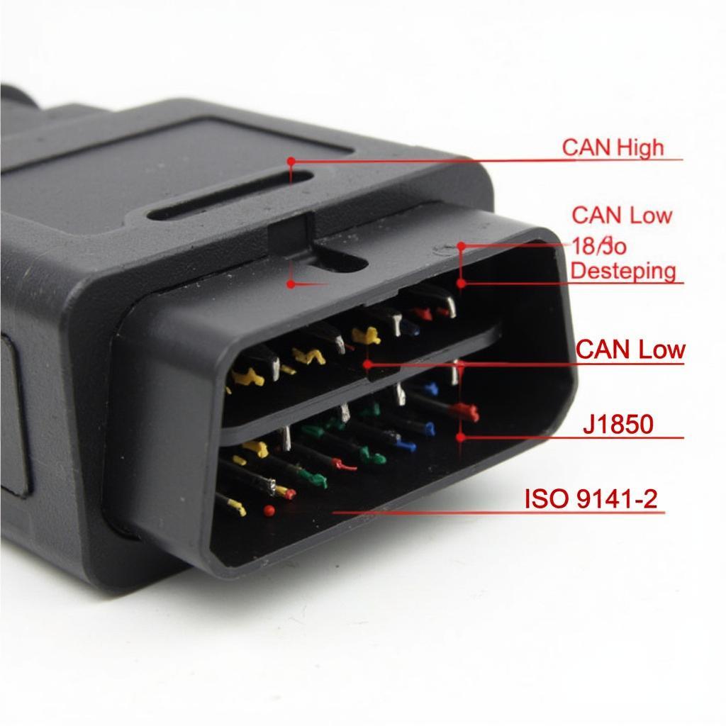
The OBD2 connector, typically located under the dashboard on the driver’s side, is the gateway to your vehicle’s diagnostic system. Each pin within this 16-pin connector has a specific function and corresponding wire color. Understanding this color-coded system is crucial for accurate diagnostics and modifications. For example, if you’re trying to tap into the vehicle’s speed sensor, the honda obd2 injector wiring diagram can help you identify the correct wire.
Standard OBD2 Wire Colors and Their Functions
While there can be some variations between manufacturers, the majority adhere to a standard color code. Here’s a breakdown of the common color OBD2 wiring diagram assignments:
- Pin 2 (J1850 Bus+): This pin is typically white/purple and used for communication on the J1850 bus system, primarily found in Ford vehicles.
- Pin 4 (Chassis Ground): Black is the standard color for chassis ground, providing a common return path for electrical circuits.
- Pin 5 (Signal Ground): Gray is usually used for signal ground, providing a reference point for sensor signals.
- Pin 6 (CAN High): High-speed CAN communication uses this pin, typically colored orange.
- Pin 7 (ISO 9141-2 K-Line): This pin, often brown/white, is used for communication on the ISO 9141-2 protocol.
- Pin 14 (CAN Low): Purple/yellow is the common color for the low-speed CAN communication line.
- Pin 15 (L-Line): Also part of the ISO 9141-2 protocol, this pin is usually colored white.
- Pin 16 (Battery Power): Red is universally used to indicate battery power.
Why is a Color OBD2 Wiring Diagram Important?
Knowing the color codes allows you to quickly identify the correct wires for various tasks, saving you time and preventing potential damage to your vehicle’s electrical system. This is especially important when installing aftermarket devices like remote starters or security systems. If you need a factory wiring diagram for reference, resources like the 2012 hyundai elantra oem factory obd2 wiring diagram are available online.
Common Applications of an OBD2 Wiring Diagram
- Troubleshooting: Identify the source of diagnostic trouble codes (DTCs) by checking the corresponding circuits.
- Installation of Aftermarket Devices: Connect devices correctly to the appropriate power, ground, and communication lines.
- Vehicle Modifications: Tap into specific sensors or actuators for custom modifications.
- Diagnostics: Monitor live data streams from various sensors to identify performance issues.
Where Can I Find a Reliable Color OBD2 Wiring Diagram?
Reliable color OBD2 wiring diagrams can be found in various resources, including vehicle repair manuals, online automotive databases, and specialized websites. Remember to always use a diagram specific to your vehicle’s make, model, and year to ensure accuracy. Resources like OBDFree provide helpful diagrams like the hondacivic 2000 obd2 port fuse information.
Tips for Using an OBD2 Wiring Diagram
- Verify Vehicle Compatibility: Always double-check that the diagram matches your specific vehicle.
- Understand Symbols: Familiarize yourself with the symbols and abbreviations used in the diagram.
- Use a Multimeter: A multimeter can be used to verify the continuity and voltage of the circuits.
- Exercise Caution: Working with automotive electrical systems can be dangerous. Disconnect the battery negative terminal before making any connections.
Conclusion
Understanding a color OBD2 wiring diagram is fundamental for anyone working with a vehicle’s diagnostic system. From troubleshooting issues to installing new devices, the knowledge of these color codes empowers you to navigate the complex world of automotive electronics with confidence. Utilizing this knowledge and resources like the 1998 buick skylark obd2 fuse information available, you can confidently tackle various automotive projects. Remember to always double-check your resources and prioritize safety when working with your vehicle’s electrical system.
FAQ
- What does OBD2 stand for? On-Board Diagnostics, generation II.
- Where is the OBD2 port located? Typically under the dashboard on the driver’s side.
- Can I damage my car by using the wrong OBD2 wiring diagram? Yes, using an incorrect diagram can lead to electrical shorts and damage.
- Are all OBD2 connectors the same? While the physical connector is standardized, the wiring and communication protocols can vary.
- What is the difference between CAN High and CAN Low? They are two wires used for differential signaling in the Controller Area Network (CAN) bus system.
- Why is ground important in an OBD2 circuit? Ground provides a return path for electrical current and a reference point for sensor signals.
- Do I need any special tools to use an OBD2 wiring diagram? A multimeter is helpful for testing circuits.
For any further assistance, feel free to contact us via WhatsApp: +1(641)206-8880, or Email: [email protected]. Our customer support team is available 24/7. You might also find useful information in our article on obd2 ケーブル 自作.


