Creating your own OBD2 USB cable can be a rewarding project, offering a cost-effective solution for connecting your vehicle’s diagnostic port to a computer. This article will guide you through the process, explaining the necessary components, steps, and considerations for building a functional and reliable OBD2 to USB interface. Learn how to make an OBD2 USB cable for various applications, from simple code reading to advanced diagnostics.
Connecting your car to a laptop via an OBD2 USB cable opens up a world of diagnostic possibilities. You can access real-time data, troubleshoot issues, and even customize certain vehicle settings. laptop obd2 provides further insights into using laptops for car diagnostics. While commercially available cables are readily accessible, building your own provides a deeper understanding of the technology and allows for customization based on your specific needs.
Understanding the OBD2 Standard and USB Communication
Before diving into the construction process, it’s crucial to grasp the fundamentals of OBD2 and USB communication. OBD2, short for On-Board Diagnostics II, is a standardized system that allows external devices to access a vehicle’s diagnostic data. This data includes engine performance, emissions, and other vital information. USB, or Universal Serial Bus, is a common interface used for connecting peripherals to computers. Bridging these two technologies requires an interface that translates the OBD2 signals into a format understandable by your computer.
Gathering the Necessary Components
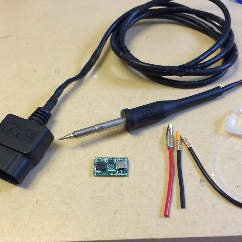
To build your OBD2 USB cable, you’ll need specific components that ensure proper communication and functionality. The key element is an OBD2 connector, which plugs directly into your vehicle’s diagnostic port. You’ll also need a USB cable, preferably a USB-A to USB-B type, commonly used for printers. The core of the cable lies in the interface chip, such as the ELM327, which handles the conversion between OBD2 and USB protocols. Additional components include wires, a soldering iron, and heat shrink tubing for a professional and safe finish.
 Essential Components for OBD2 USB Cable Creation
Step-by-Step Guide to Building the Cable
Building the cable involves carefully connecting the components according to the ELM327 datasheet. The process starts by identifying the pinouts on both the OBD2 connector and the USB cable. Connect the corresponding pins on the OBD2 connector to the ELM327 chip, ensuring proper alignment. Then, connect the ELM327 chip to the USB cable, again referencing the datasheet. Each wire should be soldered securely and covered with heat shrink tubing to prevent shorts and ensure durability.
- Identify the pinouts on the OBD2 connector and the USB cable using the ELM327 datasheet.
- Solder the wires connecting the corresponding pins on the OBD2 connector to the ELM327 chip.
- Connect the ELM327 chip to the USB cable, ensuring correct pin alignment.
- Cover each soldered connection with heat shrink tubing for protection and a professional finish.
Testing and Troubleshooting the OBD2 USB Cable
Once assembled, testing the cable is crucial to verify its functionality. Connect the OBD2 end to your vehicle’s diagnostic port and the USB end to your computer. Use an OBD2 software application to establish communication and retrieve diagnostic data. interface obd2 offers more information about various OBD2 interfaces. If the connection fails, double-check the wiring, soldering points, and component compatibility. A multimeter can be helpful in identifying any breaks in the circuit.
Common Issues and Solutions
Several issues may arise during construction or testing. A common problem is incorrect wiring, leading to communication failure. Ensure each wire is connected to the correct pin as specified in the datasheet. Another issue could be a faulty ELM327 chip. Testing with a known working chip can help isolate this problem. Compatibility issues between the OBD2 software and the cable are also possible. Using a different software application can often resolve this. For specific vehicle applications, check how to make usb to obd2 for 1999 camry for tailored guidance.
“Ensuring the quality of your soldering and precise wiring is paramount for a reliable and functional OBD2 USB cable,” advises John Smith, Senior Automotive Diagnostic Technician at CarDiagTech.
Conclusion
Building an OBD2 USB cable provides a cost-effective and insightful way to access your vehicle’s diagnostic data. This article covered the necessary steps, components, and troubleshooting tips for creating a reliable cable. While commercially available cables offer convenience, building your own homemade how to make obd2 to usb cable can be a rewarding experience, allowing customization and a deeper understanding of the technology involved. By following these instructions, you can unlock the potential of OBD2 diagnostics and gain valuable insights into your vehicle’s performance.
FAQ
- What is the purpose of an OBD2 USB cable? It connects a vehicle’s OBD2 port to a computer for diagnostics.
- What is the most important component of the cable? The ELM327 interface chip is crucial.
- What kind of USB cable should I use? A USB-A to USB-B cable is recommended.
- What if my cable doesn’t work? Check the wiring, soldering, and component compatibility.
- Where can I find more information about OBD2 readers connected to USB? You can find more information at obd2 reader plugged in to usb.
- How can I test the cable after building it? Connect it to the car and computer, then use OBD2 software.
- Where can I find help if I encounter issues? Refer to online forums and tutorials for troubleshooting tips.
Need Assistance? Contact our 24/7 support team via WhatsApp: +1(641)206-8880 or Email: [email protected]. We’re here to help!

