Understanding the OBD2 mini connector pinout is crucial for anyone working with vehicle diagnostics. This guide provides a detailed overview of the pinout, its functions, and common uses, helping you navigate the complexities of OBD2 systems.
The OBD2 standard, officially known as OBD-II (On-Board Diagnostics, Second Generation), is a system designed to monitor and report on various aspects of a vehicle’s performance. The standardized 16-pin connector, often referred to as the OBD2 mini connector, provides a common interface for accessing this valuable data. Understanding its pinout allows you to effectively utilize diagnostic tools and troubleshoot vehicle issues. You can even build your own homemade how to make obd2 to usb cable.
Decoding the OBD2 Mini Connector Pinout
The OBD2 mini connector features 16 pins, each assigned a specific function. These functions can be broadly categorized into power supply, grounding, communication protocols, and manufacturer-specific uses.
- Pin 1: Manufacturer Discretionary, or in some cases, J1850+ communication.
- Pin 2: J1850+ Bus Positive Communication Line
- Pin 3: Manufacturer Discretionary
- Pin 4: Chassis Ground
- Pin 5: Signal Ground
- Pin 6: CAN High (J-2284)
- Pin 7: ISO 9141-2 K-Line
- Pin 8: Manufacturer Discretionary, or in some cases, J1850- communication.
- Pin 9: Manufacturer Discretionary
- Pin 10: J1850- Bus Negative Communication Line
- Pin 11: Manufacturer Discretionary
- Pin 12: Manufacturer Discretionary
- Pin 13: Manufacturer Discretionary
- Pin 14: CAN Low (J-2284)
- Pin 15: ISO 9141-2 L-Line
- Pin 16: Battery Power (12V)
This standardized pinout ensures compatibility across various vehicle makes and models. Knowing the function of each pin is essential for interpreting diagnostic data and understanding how different systems interact. Are you looking for a specific sct performance obd2 cord for x4 programmer? Understanding the pinout will help you choose the right cable.
Why is the OBD2 Mini Connector Pinout Important?
The pinout provides a roadmap to the vehicle’s internal systems. By accessing specific pins, diagnostic tools can retrieve information about engine performance, emissions, transmission, and other crucial data points. This allows mechanics and vehicle owners to identify and address potential problems quickly and efficiently.
What are the Different Communication Protocols?
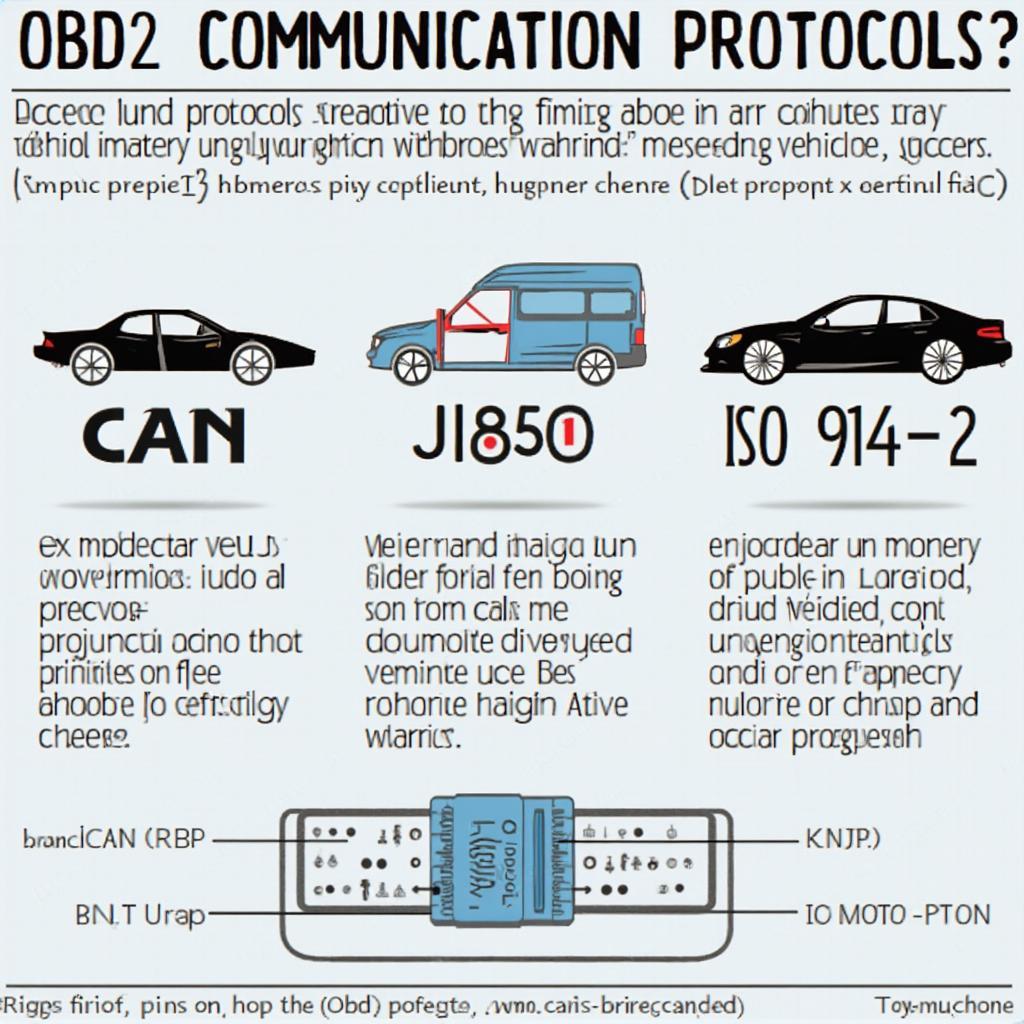
Several communication protocols are used in OBD2 systems, including CAN, J1850, and ISO 9141-2. The obd2 can j2284 protocol is becoming increasingly prevalent. Understanding these protocols and their corresponding pins is crucial for selecting compatible diagnostic tools.
Troubleshooting with the OBD2 Mini Connector Pinout
Knowing the obd2 mini connector pinout is valuable for troubleshooting various vehicle issues. For example, if you suspect a problem with the CAN communication, you can use a multimeter to check the voltage on pins 6 and 14.
“Understanding the OBD2 pinout is like having a key to unlock your car’s secrets,” says automotive expert, Dr. Emily Carter, Ph.D. “It empowers you to diagnose and address issues proactively.”
How Can I Test the OBD2 Connector?
A simple test involves checking the voltage on pin 16 (battery power) and pin 4 (chassis ground) using a multimeter. This confirms the connector is receiving power. If you’re looking for an obd2 to db9 cable, knowing the pinout will also ensure compatibility.
Conclusion
The OBD2 mini connector pinout is a fundamental aspect of vehicle diagnostics. By understanding its structure and functions, you can effectively use diagnostic tools, troubleshoot issues, and gain deeper insights into your vehicle’s performance. Mastering the obd2 mini connector pinout is a valuable skill for any car enthusiast or professional mechanic.
FAQ
- What does OBD2 stand for? OBD2 stands for On-Board Diagnostics, Second Generation.
- How many pins does an OBD2 connector have? An OBD2 connector has 16 pins.
- What is the function of pin 16? Pin 16 provides battery power (12V).
- What are the common OBD2 communication protocols? Common protocols include CAN, J1850, and ISO 9141-2.
- Where can I find more information on OBD2? Numerous online resources, forums, and technical manuals provide further information on OBD2 systems.
- What if my car doesn’t have an OBD2 port? Cars manufactured before 1996 may not have an OBD2 port.
- Can I damage my car by incorrectly using the OBD2 port? While unlikely, using incorrect tools or procedures could potentially damage the OBD2 system.
Common OBD2 Connector Issues
Some common issues include loose connections, bent pins, or corrosion. These can prevent proper communication between the diagnostic tool and the vehicle’s systems.
Related Resources
For more information on related topics, you might find resources on OBD2 adapters and diagnostic software helpful. Check out our other articles on esquema obd2.
Need help? Contact us on WhatsApp: +1(641)206-8880 or email us at [email protected]. Our customer support team is available 24/7.


