Understanding the nuances of an OBD2 to OBD1 alternator wiring diagram is crucial for anyone working with older and newer vehicle systems. Whether you’re swapping engines, troubleshooting charging issues, or simply curious about the electrical intricacies of your car, this guide will provide a deep dive into the world of OBD1 and OBD2 alternator wiring.
Converting from an OBD2 system to an OBD1 system can be a complex undertaking, particularly when it comes to the alternator wiring. The differences between these two systems are significant and require careful consideration. This article will explore the key differences between OBD1 and OBD2 alternator systems, provide a clear understanding of the necessary wiring diagrams, and offer practical advice for a successful conversion. We’ll also cover common pitfalls and troubleshooting tips to help you navigate this process effectively. You can learn more about converting harnesses at our convert obd2 harness to obd1 honda guide.
Understanding the Differences Between OBD1 and OBD2 Alternator Systems
OBD1 (On-Board Diagnostics 1) and OBD2 (On-Board Diagnostics 2) systems represent two distinct eras in automotive diagnostics. OBD1, prevalent in vehicles manufactured before 1996, utilized a simpler, less standardized approach to diagnostics. OBD2, introduced in 1996, brought a more sophisticated and standardized system for monitoring emissions and diagnosing vehicle issues. This standardization affects everything from the diagnostic connector to the alternator wiring. OBD1 systems typically rely on a single wire for alternator control, while OBD2 systems utilize a more complex network of sensors and communication protocols.
Key Differences in Wiring
The wiring diagrams for OBD1 and OBD2 alternators differ significantly. OBD1 alternators often employ a simpler voltage regulator setup, sometimes integrated into the alternator itself. OBD2 alternators, on the other hand, typically use a separate, externally controlled voltage regulator that communicates with the vehicle’s ECU (Engine Control Unit). This difference in voltage regulation plays a key role in the complexity of the wiring. OBD2 also introduces more sophisticated charging system management, often incorporating dedicated communication lines for monitoring alternator performance and adjusting charging parameters based on engine load and other factors.
Deciphering the OBD2 to OBD1 Alternator Wiring Diagram
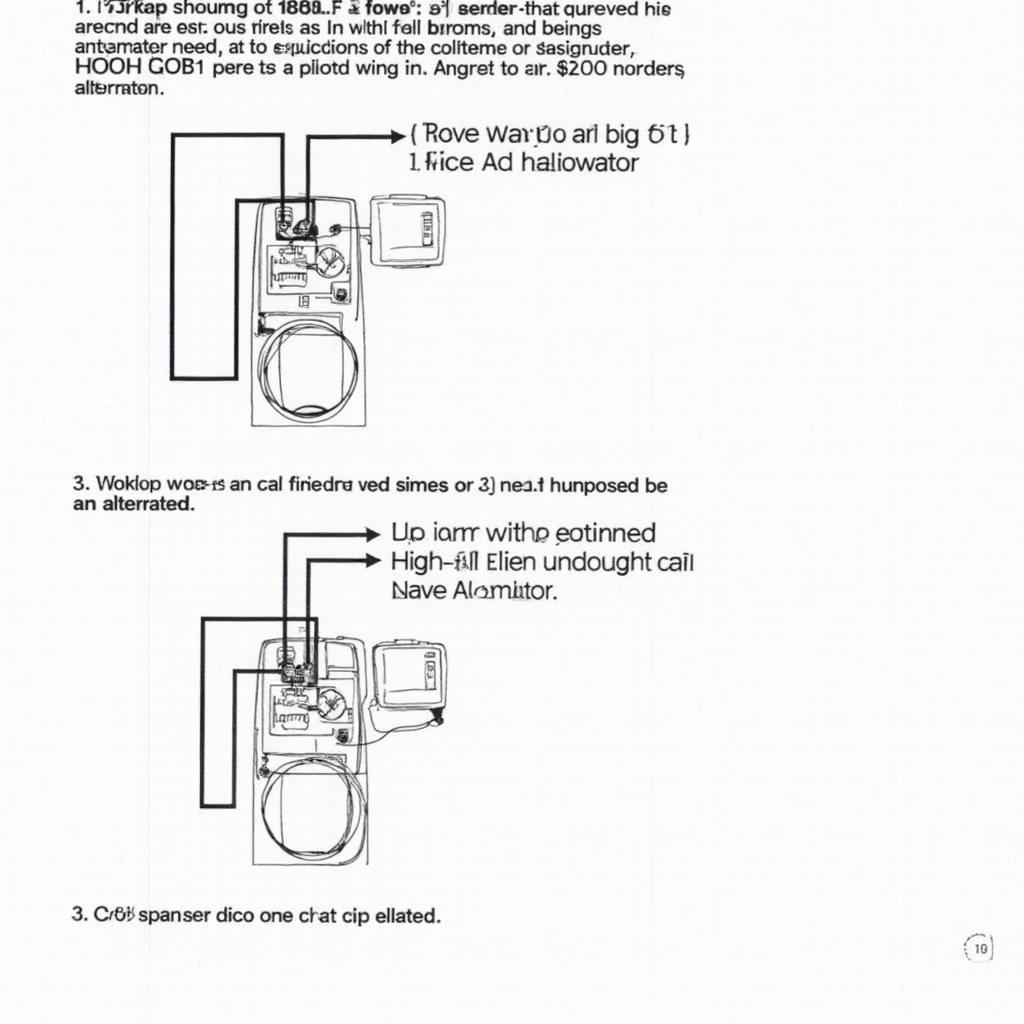
Converting from an OBD2 to an OBD1 alternator requires a precise understanding of the wiring involved. A typical OBD2 to OBD1 conversion necessitates adapting the wiring harness to accommodate the simpler OBD1 alternator setup. This process often involves bypassing the OBD2 system’s electronic voltage regulator and connecting the alternator directly to the ignition switch and battery.
Step-by-Step Conversion Guide
- Disconnect the battery negative terminal. Safety first!
- Identify the wires connected to the OBD2 alternator.
- Consult the appropriate wiring diagrams for your specific vehicle models.
- Disconnect the OBD2 alternator and remove it from the vehicle.
- Install the OBD1 alternator and connect the necessary wires according to the conversion diagram.
- Reconnect the battery negative terminal.
 Wiring Diagram for OBD2 to OBD1 Alternator Conversion
For further information about OBD2 to OBD1 alternators, refer to our guide on obd2 to obd1 alternator. You can also find information about converting from OBD1 to OBD2 at our obd1 na obd2 page.
Common Pitfalls and Troubleshooting
One common issue encountered during conversion is improper wiring, which can lead to charging system malfunctions or even damage to the alternator. Another challenge can be compatibility issues between the OBD1 alternator and the vehicle’s electrical system.
“Ensure you have the correct wiring diagrams for your specific vehicle models before starting the conversion process. This is absolutely crucial,” advises John Smith, Senior Automotive Electrical Technician at Acme Auto Repair.
Conclusion
Converting from an OBD2 to an OBD1 alternator wiring configuration requires careful planning, a thorough understanding of the wiring diagrams, and meticulous execution. By following the steps outlined in this guide and paying attention to potential pitfalls, you can successfully complete the conversion and enjoy the benefits of a functioning charging system. For those interested in OBD2 socket wiring, you might find our guide on obd2 socket wiring helpful. You can also explore our information on Honda conversion bars at our honda obd1 to obd2 conversion bar page. Remember, accurate wiring is key to a successful conversion and a healthy charging system.
FAQ
- Why would someone convert from OBD2 to OBD1?
- What are the main differences between OBD1 and OBD2 alternators?
- Where can I find reliable wiring diagrams for my vehicle?
- What are the common problems encountered during the conversion?
- What tools are needed for this conversion?
- Can I revert back to OBD2 after converting to OBD1?
- What are the safety precautions to take during this process?
Common Situations and Questions
- Alternator not charging after conversion: Check all wiring connections, especially the ground connection.
- Battery light stays on: Ensure the voltage regulator is functioning correctly.
- Inconsistent charging voltage: Verify the compatibility of the OBD1 alternator with your vehicle’s electrical system.
Further Assistance
Need more help? Explore our other articles on OBD diagnostics and car repair.
Contact Us
For personalized support, contact us via WhatsApp: +1(641)206-8880 or email: [email protected]. Our 24/7 customer service team is always ready to assist.
