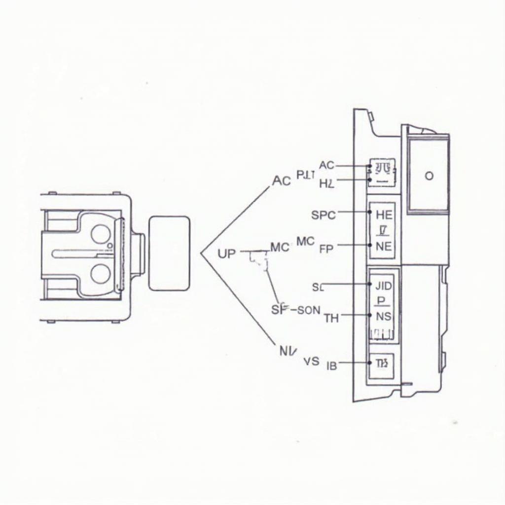
The OBD2 connector pin diagram is a crucial roadmap for anyone working with vehicle diagnostics. Understanding its layout unlocks a wealth of information about your car’s performance and health. This article provides a comprehensive guide to the OBD2 connector, exploring its pinout, functions, and common uses. You’ll be equipped to interpret diagnostic trouble codes (DTCs) and gain a deeper understanding of your vehicle’s systems.
The OBD2 (On-Board Diagnostics, version 2) system is a standardized system found in most vehicles manufactured after 1996. It allows technicians and car owners to access diagnostic information about the vehicle’s various electronic control units (ECUs). The system works through a standardized 16-pin connector, often located under the dashboard on the driver’s side. Knowing how to navigate the obd2 connector pin diagram is essential for effective vehicle troubleshooting. Want to know where your Avalon’s port is located? Check our guide on the 98 avalon obd2 port location.
Unveiling the Secrets of the OBD2 Connector Pin Diagram
The 16 pins of the OBD2 connector are not assigned randomly. Each pin serves a specific purpose, connecting to different communication networks and power sources within the vehicle. This standardized layout ensures compatibility across various vehicle makes and models. Familiarizing yourself with the obd2 connector pin diagram empowers you to perform diagnostics with confidence.
Pin 1: Primarily used by the manufacturer for specific communication protocols.
Pin 2: Part of the J1850 PWM communication bus used by some manufacturers.
Pin 3: Reserved for future use.
Pin 4: Chassis Ground.
Pin 5: Signal Ground.
Pin 6: CAN High (Controller Area Network).
Pin 7: K-Line ISO 9141-2 and ISO 14230-4.
Pin 8: Reserved for future use.
Pin 9: Reserved for future use.
Pin 10: J1850 Bus+
Pin 11: Reserved for future use.
Pin 12: Reserved for future use.
Pin 13: Reserved for future use.
Pin 14: CAN Low (Controller Area Network).
Pin 15: L-Line ISO 9141-2 and ISO 14230-4.
Pin 16: Battery Power.
Understanding the Different Communication Protocols
The OBD2 system uses several communication protocols, including CAN, J1850, and ISO 9141-2/14230-4. Each protocol utilizes specific pins on the connector to transmit data between the scan tool and the vehicle’s ECUs. This allows for seamless communication and retrieval of diagnostic information. Do you know if your 2008 Honda Element has an OBD2 port? Find out in our does 2008 honda element have obd2 port guide.
CAN (Controller Area Network)
CAN is a high-speed, robust communication protocol used in many modern vehicles. It utilizes pins 6 (CAN High) and 14 (CAN Low) for data transmission.
J1850
J1850 is another communication protocol used primarily by domestic vehicle manufacturers. It has two variations: PWM (Pulse Width Modulation) and VPW (Variable Pulse Width). PWM uses pin 2, while VPW uses pins 10 (Bus+) and 2 (Bus-).
ISO 9141-2 and ISO 14230-4
These protocols are commonly used in European and Asian vehicles. They utilize pins 7 (K-Line) and 15 (L-Line) for communication.
Common Uses of the OBD2 Connector Pin Diagram
Knowing the obd2 connector pin diagram is crucial for several tasks:
- Diagnosing Trouble Codes (DTCs): The OBD2 connector allows access to DTCs, which indicate specific problems within the vehicle’s systems.
- Monitoring Vehicle Performance: Real-time data from various sensors can be accessed through the connector, allowing for monitoring of engine parameters, emissions, and other critical data.
- Programming and Customization: Some vehicles allow for programming and customization of certain features through the OBD2 port.
- Emissions Testing: Emissions testing centers utilize the OBD2 connector to verify compliance with environmental regulations.
Looking for the OBD2 port on your Subaru Forester? Our guide on the subaru forester obd2 port location can help.
“Understanding the obd2 connector pin diagram is like having a key to your car’s brain,” says automotive expert, Dr. James Carter. “It allows you to unlock valuable information and address issues efficiently.”
“By learning the basics of the obd2 connector pin diagram, car owners can take a more proactive approach to vehicle maintenance,” adds Emily Davis, a seasoned mechanic.
Conclusion
The obd2 connector pin diagram is a fundamental element of modern vehicle diagnostics. By understanding its layout and the various communication protocols it supports, you can gain valuable insights into your car’s performance and troubleshoot issues effectively. Mastering the obd2 connector pin diagram is a must for any car enthusiast or professional technician. Need to bridge OBD2 pins? Check out our guide on how to bridge obd2 pins.
FAQ
-
What is the OBD2 connector pin diagram?
The OBD2 connector pin diagram shows the function of each of the 16 pins on the standard OBD2 connector. -
Why is understanding the pin diagram important?
Understanding the pin diagram helps you use diagnostic tools effectively and troubleshoot car problems. -
What are the main communication protocols used by OBD2?
The main protocols are CAN, J1850, and ISO 9141-2/14230-4. -
Where can I find the OBD2 port in my car?
The OBD2 port is usually located under the dashboard on the driver’s side. -
What can I do with an OBD2 scanner and the pin diagram knowledge?
You can read diagnostic trouble codes, monitor vehicle performance, and sometimes even program certain features. -
Are all OBD2 connectors the same?
Yes, all OBD2 connectors follow the same 16-pin standard, ensuring compatibility across different vehicle makes and models. -
What if my car is older than 1996?
Cars manufactured before 1996 might have different diagnostic connectors or systems.
Need more help? Check out our comprehensive guide on the obd2 16 pin connector diagram.
If you need further assistance or have specific questions, please don’t hesitate to contact us via WhatsApp: +1(641)206-8880, Email: [email protected] or visit us at 789 Elm Street, San Francisco, CA 94102, USA. Our customer service team is available 24/7 to assist you.


