Wiring VTEC in your OBD2 Honda can seem daunting, but with the right knowledge and preparation, it’s a manageable task. This guide provides a step-by-step approach to wiring VTEC for your OBD2 Honda, covering everything from understanding the system to troubleshooting common issues.
Understanding VTEC in OBD2 Systems
VTEC (Variable Valve Timing and Lift Electronic Control) is Honda’s innovative system for optimizing engine performance across the RPM range. In OBD2 systems, VTEC is controlled electronically, using sensors and actuators managed by the ECU. This allows for precise control over valve timing and lift, resulting in improved fuel efficiency at lower RPMs and increased power at higher RPMs. Understanding this fundamental principle is crucial before diving into the wiring process.
After the initial introduction to VTEC, understanding the different types of VTEC systems in OBD2 Hondas is essential. While the core concept remains the same, there are variations in implementation, such as single-stage and multi-stage VTEC. Knowing which system your car has will guide you in choosing the right wiring approach. A detailed grasp of these variations will ultimately contribute to a successful VTEC wiring project. Check out our guide on obd2 gsr swap for more specific swap information.
Preparing for the Wiring Process
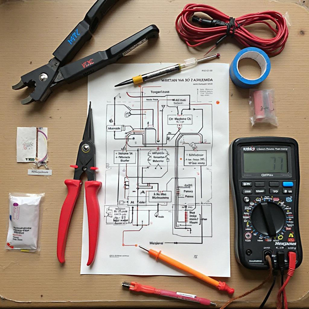
Before starting the wiring, gather the necessary tools and materials. This includes a wiring diagram specific to your Honda model, wire strippers, crimpers, electrical tape, connectors, and a multimeter for testing continuity. Having the right tools readily available will streamline the process and prevent unnecessary delays. Moreover, ensure your work area is clean and well-lit to avoid mistakes and ensure safety.
Disconnect the battery’s negative terminal before beginning any wiring work. This crucial safety step prevents accidental shorts and protects the car’s electrical system.
Step-by-Step VTEC Wiring Guide
- Locate the VTEC solenoid: The VTEC solenoid is typically located on the cylinder head, near the valve cover. Consult your wiring diagram for the exact location.
- Identify the wiring harness: The VTEC wiring harness connects the solenoid to the ECU. Trace the wires from the solenoid to the ECU connector.
- Connect the power wire: The VTEC solenoid requires a 12V power source switched by the ignition. Connect this wire to the appropriate pin on the ECU connector, as indicated in the wiring diagram. For some specific harnesses, check out our rywire obd2 harness page.
- Connect the ground wire: Ensure a secure ground connection for the VTEC solenoid. This can be done by connecting the ground wire to a suitable chassis ground point.
- Connect the control wire: The control wire from the ECU activates the VTEC solenoid. Connect this wire to the corresponding pin on the ECU connector. You may find our guide on ls vtec with obd2 gsr harness helpful.
- Connect the pressure switch: The VTEC pressure switch ensures the system only activates when the oil pressure is sufficient. Connect the pressure switch wiring according to your specific model’s wiring diagram. Our honda obd2 crankshaft position sensor with wiring harness guide may also be relevant.
- Test the wiring: After completing the wiring, reconnect the battery and test the VTEC system by running the engine and observing the VTEC engagement.
Troubleshooting Common VTEC Wiring Issues
- VTEC not engaging: Check for loose connections, blown fuses, or a faulty VTEC solenoid. Use a multimeter to test the continuity of the wiring. Consider checking out our rywire obd2 to obd1 vtec sub harness if you’re working with an OBD1 conversion.
- Check Engine Light (CEL) illuminated: Retrieve the OBD2 trouble codes using a scanner to diagnose the specific issue. This will provide valuable insights into the problem.
- Erratic VTEC engagement: This could be caused by a faulty pressure switch or wiring issues. Inspect the wiring and replace the pressure switch if necessary.
Conclusion
Wiring VTEC in your OBD2 Honda requires careful attention to detail and a thorough understanding of the system. By following this comprehensive guide and taking the necessary precautions, you can successfully wire VTEC and unlock the full potential of your Honda engine. Remember to always consult your specific model’s wiring diagram and seek professional assistance if needed.
FAQ
- What is VTEC? VTEC is Honda’s variable valve timing system that optimizes engine performance.
- Do all OBD2 Hondas have VTEC? No, not all OBD2 Hondas have VTEC.
- What tools do I need to wire VTEC? You’ll need a wiring diagram, wire strippers, crimpers, electrical tape, connectors, and a multimeter.
- Is it safe to wire VTEC myself? Yes, but always disconnect the battery before working on the electrical system.
- What should I do if VTEC isn’t engaging? Check for loose connections, blown fuses, or a faulty VTEC solenoid.
- Why is my Check Engine Light on after wiring VTEC? Retrieve the OBD2 codes to diagnose the issue.
- What if VTEC is engaging erratically? Check the pressure switch and wiring.
For further assistance, please contact us via WhatsApp: +1(641)206-8880, Email: [email protected] or visit our office at 789 Elm Street, San Francisco, CA 94102, USA. Our customer support team is available 24/7.


