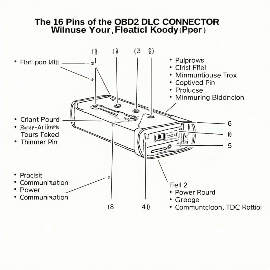
The OBD2 DLC connector pinout is your gateway to a vehicle’s internal systems. Knowing how to navigate this crucial interface allows you to diagnose issues, monitor performance, and unlock valuable data from your car. This comprehensive guide delves into the intricacies of the OBD2 connector, providing you with the knowledge you need to confidently use your OBD2 scanner.
The OBD-II Data Link Connector (DLC) is a standardized 16-pin port found in most vehicles manufactured after 1996. It serves as the primary interface for connecting a diagnostic scan tool to retrieve vehicle information. Understanding the obd2 dlc connector pinout is essential for anyone working with vehicle diagnostics. The specific functions of each pin can vary slightly between manufacturers, but they generally adhere to a standardized format.
Let’s break down the typical pin assignments and explore the purpose of each connection. Having a clear understanding of this will enable you to troubleshoot more effectively and interpret data accurately. Remember, using the correct pinout is essential for safe and successful diagnostics.
Decoding the OBD2 DLC Connector Pinout
The OBD2 standard defines the pinout for the DLC, ensuring compatibility across various vehicle makes and models. While some manufacturers may use specific pins for proprietary functions, the core functionality remains consistent. This standardization is key for universal OBD2 scanners.
- Pin 1: Not used in most applications. Some manufacturers may utilize this pin for proprietary communication.
- Pin 2: J1850 Bus+ (Ford and GM vehicles). This pin carries data for the J1850 PWM protocol.
- Pin 3: Not used in most applications.
- Pin 4: Chassis Ground. Provides a ground connection for the diagnostic tool.
- Pin 5: Signal Ground. A ground reference for sensor signals.
- Pin 6: CAN High (J-2284). Part of the Controller Area Network (CAN) communication system.
- Pin 7: ISO 9141-2 K-Line. Used for communication in some European and Asian vehicles.
- Pin 8: Not used in most applications.
- Pin 9: Not used in most applications.
- Pin 10: J1850 Bus- (Ford and GM vehicles). Completes the J1850 PWM communication circuit.
- Pin 11: Not used in most applications.
- Pin 12: Not used in most applications.
- Pin 13: Not used in most applications.
- Pin 14: CAN Low (J-2284). Completes the CAN communication circuit.
- Pin 15: ISO 9141-2 L-Line. Used for communication in some European and Asian vehicles.
- Pin 16: Battery Power. Supplies power to the diagnostic tool.
If you are looking for more specific information about certain car models, you can check out our guides on the 2011 Chevy truck obd2 pin schematic and the obd2 pinout for gm cars malibu 2012.
Why Understanding the Pinout Matters
Knowing the obd2 dlc connector pinout can be invaluable in several situations:
- Troubleshooting Connection Issues: If your OBD2 scanner isn’t connecting, checking the relevant pins for power and ground can help identify the problem. You might even find that your obd2 port has power but wont connect.
- Advanced Diagnostics: Understanding which pins correspond to specific communication protocols can aid in advanced diagnostics and troubleshooting.
- DIY Repairs: Knowing the pinout allows you to perform some basic diagnostics and repairs yourself.
- Compatibility: Ensures you’re using the correct cable and adapter for your vehicle and scan tool. For example, understanding obd2 protocol iso cable can be crucial for certain vehicles.
Common Questions About the OBD2 DLC Connector Pinout
What if my car doesn’t have a 16-pin connector?
Some older vehicles may use different connectors. However, adapters are available to connect an OBD2 scanner.
Can I damage my car by probing the OBD2 connector?
While generally safe, using incorrect tools or probing the wrong pins can potentially damage the vehicle’s electronics.
What does DLC stand for?
DLC stands for Data Link Connector. It’s the standardized port that allows communication with the vehicle’s onboard computer.
John Smith, a seasoned automotive technician with over 20 years of experience, emphasizes, “Understanding the OBD2 pinout is like knowing the language of your car. It allows you to communicate with its internal systems and understand what’s going on.”
Conclusion
The obd2 dlc connector pinout provides a vital link to your vehicle’s internal workings. Mastering this knowledge allows you to perform diagnostics, understand your car better, and potentially save money on repairs. By understanding the function of each pin, you can unlock a wealth of information about your vehicle’s performance and health. Check out our guide on the obd2 plug subaru legacy for more specific information.
FAQ:
-
What is the purpose of the OBD2 DLC connector? It allows communication between a diagnostic tool and the vehicle’s computer.
-
Are all OBD2 connectors the same? Yes, the 16-pin connector is standardized, but pin functions may vary slightly.
-
Do I need to know the pinout to use an OBD2 scanner? No, most scanners handle communication automatically.
-
What is CAN communication? Controller Area Network (CAN) is a high-speed communication system used in modern vehicles.
-
What are the J1850 protocols? These are communication protocols used primarily by Ford and GM vehicles.
Need more assistance? Contact us via WhatsApp: +1(641)206-8880, Email: cardiagtechworkshop@gmail.com or visit us at 789 Elm Street, San Francisco, CA 94102, USA. We offer 24/7 customer support.
