Understanding OBD2 MAP sensor wire colors is crucial for diagnosing and troubleshooting engine performance issues. This guide provides a detailed look at MAP sensor wiring, common color codes, and how to identify them effectively. We’ll cover various vehicle makes and models, offer troubleshooting tips, and empower you to confidently tackle MAP sensor related problems.
Locating and identifying the correct wires for your vehicle’s Manifold Absolute Pressure (MAP) sensor can be tricky. While there are some common color schemes, they can vary significantly between manufacturers and even model years. This guide aims to provide a clear understanding of OBD2 MAP sensor wire colors, helping you avoid misdiagnosis and potential damage to your vehicle’s electrical system. Check out our guide on the 06 mustang obd2 wire colors for more specific information.
Understanding the MAP Sensor and Its Function
The MAP sensor is a critical component in your vehicle’s engine management system. It measures the air pressure inside the intake manifold, providing essential data to the Engine Control Unit (ECU). The ECU uses this information to calculate air density and determine the optimal fuel mixture for combustion. A faulty MAP sensor can lead to a range of performance problems, including poor fuel economy, rough idling, and reduced power.
Common OBD2 MAP Sensor Wire Colors
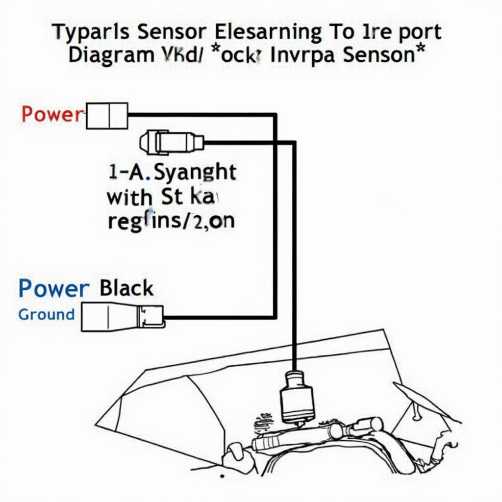
While standardized color codes for MAP sensor wires would simplify diagnostics, the reality is far more complex. Manufacturers often use different color schemes, making it necessary to consult your vehicle’s wiring diagram for accurate information. However, some common color codes exist. These include:
- Red: Often used for the power supply wire (5V).
- Black or Green: Typically represents the ground wire.
- Blue or Gray: Commonly used for the signal wire.
It’s crucial to remember these are just general guidelines. Always verify the wire colors against your vehicle’s specific wiring diagram before making any connections or adjustments. You can find more resources on OBD2 wiring diagrams on our website, like this toyota obd2 wiring diagram.
Troubleshooting MAP Sensor Issues
If you suspect a faulty MAP sensor, several diagnostic steps can help pinpoint the problem. These include:
- Visually inspect the sensor and wiring: Look for any signs of damage, corrosion, or loose connections.
- Check for vacuum leaks: A leak in the vacuum hose connected to the MAP sensor can affect its readings.
- Use a multimeter to test the sensor’s voltage and resistance: Compare your readings with the manufacturer’s specifications.
“A multimeter is an invaluable tool for diagnosing MAP sensor problems,” says John Miller, a seasoned automotive technician with over 20 years of experience. “By measuring the voltage and resistance, you can quickly determine if the sensor is functioning correctly.” Remember to consult your vehicle’s specific repair manual for detailed testing procedures.
Identifying Your Vehicle’s Specific MAP Sensor Wire Colors
The most reliable way to determine your vehicle’s MAP sensor wire colors is to consult its wiring diagram. This diagram provides a detailed schematic of the electrical system, including the color codes for all wires. You can typically find this diagram in your vehicle’s repair manual or online resources. OBDFree provides a comprehensive collection of wiring diagrams for various vehicle makes and models.
“Always double-check the wire colors with your vehicle’s wiring diagram before performing any work,” advises Susan Davis, an electrical engineer specializing in automotive systems. “This will help avoid costly mistakes and ensure accurate diagnostics.” You can also find helpful resources like this obd2 wiring diagram honda on our site.
Conclusion
Understanding OBD2 MAP sensor wire colors is essential for accurate diagnostics and effective troubleshooting. While common color codes exist, always consult your vehicle’s specific wiring diagram for accurate information. By following the tips and guidelines outlined in this guide, you can confidently diagnose and resolve MAP sensor-related issues, ensuring optimal engine performance. Check out our resource on obd2 gsr engine harness diagram for further reading on engine harnesses. For model-specific wiring diagrams, you might find the 2012 hyundai elantra oem factory obd2 wiring diagram helpful.
FAQ
-
What is the function of a MAP sensor?
A MAP sensor measures air pressure in the intake manifold to help the ECU determine the optimal fuel mixture. -
What are the common OBD2 MAP sensor wire colors?
Common colors include red for power, black or green for ground, and blue or gray for signal. -
How can I identify my vehicle’s specific MAP sensor wire colors?
Consult your vehicle’s wiring diagram. -
What problems can a faulty MAP sensor cause?
A faulty MAP sensor can cause poor fuel economy, rough idling, and reduced power. -
How can I test a MAP sensor?
Use a multimeter to test the sensor’s voltage and resistance. -
Where can I find my vehicle’s wiring diagram?
You can usually find it in your vehicle’s repair manual or online resources. -
What should I do if I’m unsure about working on my vehicle’s electrical system?
Consult a qualified mechanic.
Need help with your car diagnostics? Contact our 24/7 support team via WhatsApp: +1(641)206-8880, Email: [email protected] or visit us at 789 Elm Street, San Francisco, CA 94102, USA.


