An OBD2 wiring diagram is essential for anyone working with vehicle diagnostics. It provides a visual representation of the communication network between the OBD2 port and the various vehicle control modules. Whether you’re a professional mechanic or a DIY enthusiast, understanding the OBD2 wiring diagram can significantly enhance your troubleshooting capabilities.
Decoding the OBD2 Wiring Diagram
The OBD2 wiring diagram isn’t just a random collection of lines and connectors. It’s a carefully structured roadmap that guides you through the complex network of your vehicle’s electronic systems. 2000 ford f350 obd2 wiring diagram can be particularly useful for those working with older vehicles. Each wire in the diagram represents a specific communication channel, carrying vital data between the OBD2 port and various control modules. This data allows you to diagnose problems, monitor performance, and even customize certain vehicle functions.
What information does an OBD2 wiring diagram provide?
An OBD2 wiring diagram provides crucial information about the physical layout and connectivity of the OBD2 system. It typically includes:
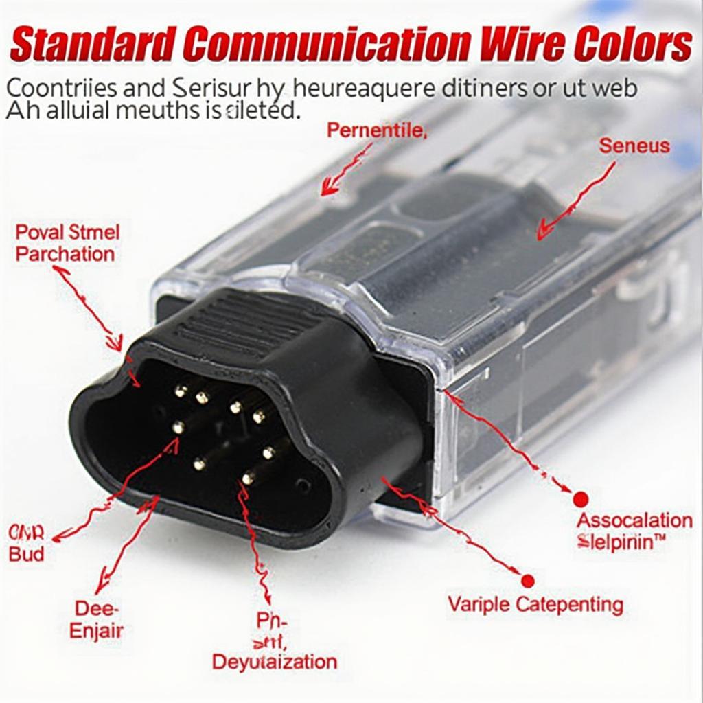
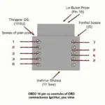
- Pinout configuration of the OBD2 connector: This shows the function of each pin on the connector, such as power, ground, and communication lines.
- Wire color codes: These codes help you identify specific wires and their corresponding functions within the system. color obd2 wiring diagram provides further details.
- Connector locations: The diagram shows where the OBD2 connector is located in the vehicle, as well as the locations of related components and modules.
- Signal descriptions: It outlines the type of data transmitted through each wire, enabling a deeper understanding of the communication protocol.
“A clear understanding of the obd2 wiring diagram empowers mechanics to pinpoint issues accurately and efficiently, saving valuable time and resources.” – John Miller, Automotive Diagnostics Specialist.
Using the OBD2 Wiring Diagram for Troubleshooting
Imagine your check engine light illuminates. Instead of blindly guessing the cause, you can use the 05 dodge 3500 obd2 wiring diagram (if applicable to your vehicle) alongside an OBD2 scanner to retrieve specific diagnostic trouble codes (DTCs). Then, consult the wiring diagram to trace the communication path related to the faulty component. This pinpoint accuracy saves time and money.
How do I locate my car’s specific OBD2 wiring diagram?
Finding the correct OBD2 wiring diagram for your car is crucial for accurate diagnostics. Several resources can help:
- Vehicle repair manuals: These manuals often contain detailed wiring diagrams specific to your car’s make and model.
- Online databases: Numerous online resources provide access to a vast library of OBD2 wiring diagrams.
- Automotive forums and communities: These platforms can be helpful in finding information shared by other car enthusiasts and professionals.
“The OBD2 wiring diagram is like a detective’s map, leading you directly to the source of the problem.” – Maria Sanchez, Senior Automotive Engineer.
Beyond Basic Diagnostics
The obd2 wiring diagram is not just for troubleshooting. It’s also valuable for advanced tasks like:
- Installing aftermarket accessories: Understanding the wiring diagram helps ensure proper integration with the vehicle’s electrical system.
- Customizing vehicle features: Advanced users can modify certain functions by accessing specific communication lines.
- Understanding vehicle communication protocols: The diagram provides insights into how different modules communicate, furthering your knowledge of the OBD2 system. 2012 hyundai elantra oem factory obd2 wiring diagram is an example of a diagram specific to a particular model.
In conclusion, the obd2 wiring diagram is a powerful tool for understanding and interacting with your vehicle’s electronic systems. Whether you’re a seasoned mechanic or just starting out, mastering the obd2 wiring diagram will undoubtedly improve your diagnostic capabilities and deepen your understanding of your vehicle. 2003 silverado obd2 wiring diagram can be a great resource for owners of this specific model.
FAQ
- What does OBD2 stand for? OBD2 stands for On-Board Diagnostics, Generation Two.
- Where can I find the OBD2 port in my car? The OBD2 port is typically located under the dashboard on the driver’s side.
- Are all OBD2 connectors the same? While the connector itself is standardized, the wiring and communication protocols can vary between vehicles.
- What is a DTC? A DTC is a Diagnostic Trouble Code, which indicates a specific malfunction within the vehicle’s systems.
- Can I damage my car by using the OBD2 port incorrectly? While unlikely, it is possible to damage the OBD2 system if incorrect procedures are followed.
- Do I need specialized equipment to use an OBD2 wiring diagram? While a multimeter can be helpful, a basic understanding of the diagram can be valuable on its own.
- What if I can’t find my car’s specific wiring diagram? Consult online resources, repair manuals, or seek assistance from automotive professionals.
Need help with your car diagnostics? Contact us via WhatsApp: +1(641)206-8880, Email: [email protected] or visit us at 789 Elm Street, San Francisco, CA 94102, USA. Our 24/7 customer support team is ready to assist you.


