Understanding OBD2 pinout color codes is crucial for anyone working with vehicle diagnostics. Whether you’re a professional mechanic or a DIY enthusiast, knowing what each wire represents can save you time and frustration. This article will delve into the intricacies of OBD2 pinout colors, providing a comprehensive guide to help you navigate the complexities of your vehicle’s diagnostic system.
The OBD2, or On-Board Diagnostics II, system is a standardized system that allows you to access your vehicle’s diagnostic information. This system uses a 16-pin connector, and each pin has a specific function and corresponding color code. Knowing these color codes can help you identify issues with your vehicle’s sensors, modules, and other components. Understanding the obd2 wiring diagram can greatly enhance your diagnostic capabilities.
Decoding the OBD2 Pinout Colors
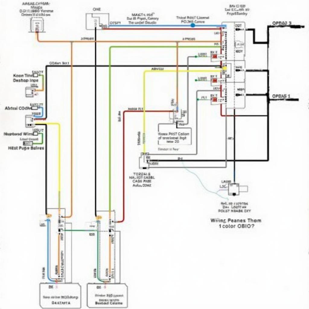
Each pin on the OBD2 connector is assigned a specific function, ranging from power and ground to communication lines for various control modules. Here’s a breakdown of the standard OBD2 pinout color codes:
- Pin 1 (Manufacturer Discretionary): This pin’s function and color can vary depending on the manufacturer.
- Pin 2 (J1850 Bus+): Primarily used in Ford vehicles, this pin is typically associated with a white/blue wire.
- Pin 3 (Manufacturer Discretionary): Similar to pin 1, this pin’s function and color are manufacturer-specific.
- Pin 4 (Chassis Ground): This pin provides a ground connection and is usually represented by a black wire.
- Pin 5 (Signal Ground): This ground connection is commonly associated with a black/white wire.
- Pin 6 (CAN High (J-2284)): Used for high-speed CAN communication, this pin is typically orange.
- Pin 7 (ISO 9141-2 K-Line): Often found in older vehicles, this communication line is usually associated with a brown/white wire.
- Pin 8 (Manufacturer Discretionary): This pin is also manufacturer-specific.
- Pin 9 (Manufacturer Discretionary): The function and color of this pin vary by manufacturer.
- Pin 10 (J1850 Bus-): Typically found in Ford vehicles, this pin is usually black/red.
- Pin 11 (Manufacturer Discretionary): The function and color of this pin are determined by the manufacturer.
- Pin 12 (Manufacturer Discretionary): This pin is also manufacturer-specific.
- Pin 13 (Manufacturer Discretionary): The function and color of this pin vary by manufacturer.
- Pin 14 (CAN Low (J-2284)): Used for low-speed CAN communication, this pin is typically purple/white.
- Pin 15 (ISO 9141-2 L-Line): Often found in older vehicles, this communication line is usually yellow.
- Pin 16 (Battery Power): This pin provides power to the OBD2 connector and is generally red.
 OBD2 Wiring Diagram with Color Explanations
Why Knowing OBD2 Pinout Colors is Important
Understanding these color codes can be immensely helpful in diagnosing vehicle problems. For instance, if you’re experiencing communication issues with a specific module, knowing the corresponding pin and wire color can help you quickly trace the problem.
“Knowing the OBD2 pinout colors is like having a roadmap to your vehicle’s electronic systems,” says automotive electronics expert, Dr. Emily Carter. “It allows you to quickly identify and troubleshoot issues, saving you valuable time and effort.”
Troubleshooting with OBD2 Pinout Colors
Using a multimeter and the obd2 wiring schematic, you can test the integrity of the wiring and pinpoint connectivity problems. This knowledge also comes in handy when installing aftermarket devices that connect to the OBD2 port, ensuring compatibility and proper functionality. If you need to check the status of your OBD2 system, consider using an obd2 led light.
Common OBD2 Pinout Color Questions
What if my car’s wiring doesn’t match the standard colors? While most vehicles adhere to the standard color codes, some manufacturers may use different colors. Consult your vehicle’s wiring diagram or a reliable online resource like h22 obd1 to obd2 distributor wiring for specific information regarding your car’s OBD2 pinout colors. Remember, accurate information is crucial for effective diagnostics. “Having the correct wiring information is paramount, especially when dealing with complex vehicle electronics,” adds Dr. Carter. “Always double-check the specific pinout for your vehicle to avoid potential misdiagnoses.”
Conclusion
Understanding OBD2 pinout color codes is essential for anyone who works on vehicles. This knowledge enables efficient diagnostics and troubleshooting, saving time and potential headaches. This comprehensive guide provides the necessary information to navigate the intricacies of your vehicle’s OBD2 system, empowering you to take control of your car’s health. Remember, having a solid understanding of your vehicle’s OBD2 system is a valuable asset for any car owner or professional mechanic.
FAQ
- What does OBD2 stand for? OBD2 stands for On-Board Diagnostics II.
- How many pins are in an OBD2 connector? There are 16 pins in a standard OBD2 connector.
- Where can I find the specific OBD2 pinout for my car? Consult your vehicle’s wiring diagram or a reliable online resource.
- What is the purpose of the different pin colors? Each color represents a specific function or communication line within the vehicle’s diagnostic system.
- Can I use this information to install aftermarket devices? Yes, knowing the pinout colors is crucial for correctly connecting aftermarket devices to the OBD2 port.
- What should I do if my car’s wiring doesn’t match the standard colors? Consult your vehicle’s specific wiring diagram.
- Where can I find more information about OBD2 systems? Online resources and automotive forums can provide additional information.
Need further assistance with your OBD2 system? Contact us via WhatsApp: +1(641)206-8880, Email: [email protected] or visit us at 789 Elm Street, San Francisco, CA 94102, USA. Our customer support team is available 24/7 to answer your questions. You might also find helpful information on our pages about obd2 vr6 wiring diagram.

