Your cart is currently empty!

Understanding the OBD2 Pin Layout
The Obd2 Pin Layout, a standardized 16-pin connector, is your gateway to your vehicle’s internal systems. It allows diagnostic tools, like OBD2 scanners, to communicate with your car’s computer and access valuable data about its performance and health. Understanding this layout is crucial for anyone who wants to delve deeper into vehicle diagnostics.
Decoding the OBD2 Pinout: A Comprehensive Guide
The OBD2 standard, while seemingly complex, follows a logical structure. Each pin within the 16-pin connector has a specific function, ranging from power supply to data transmission. Knowing what each pin does can be immensely helpful for troubleshooting connectivity issues or understanding the data your scanner is receiving. Let’s break down the key functions of each pin:
- Pin 2 (J1850 Bus+): Used for communication in some Chrysler, Ford, and GM vehicles.
- Pin 4 (Chassis Ground): Provides a ground connection for the scanner.
- Pin 5 (Signal Ground): A ground for the data signals.
- Pin 6 (CAN High (J-2284)): Used for high-speed CAN communication.
- Pin 7 (ISO 9141-2 K-Line): A communication line used in many European and Asian vehicles.
- Pin 14 (CAN Low (J-2284)): Completes the CAN communication circuit with Pin 6.
- Pin 16 (Battery Power): Supplies power to the OBD2 scanner.
Other pins are manufacturer-specific or reserved for future use. You can find [obd2 you can buy at store] to start your diagnostic journey.
Why is the OBD2 Pin Layout Important?
Understanding the [obd2 connector pin layout] is more than just technical trivia. It empowers you to troubleshoot connection problems effectively. If your scanner isn’t communicating with your vehicle, checking the pins for damage or corrosion can often pinpoint the issue.
What if you’re dealing with an LS swap and need to connect your OBD2 gauges? A solid understanding of the [obd2 gauges ls swap] and the pin layout becomes invaluable.
“Knowing the OBD2 pin layout is like having a roadmap to your car’s brain,” says John Miller, a seasoned automotive diagnostician. “It allows you to understand the language your car speaks and diagnose problems more efficiently.”
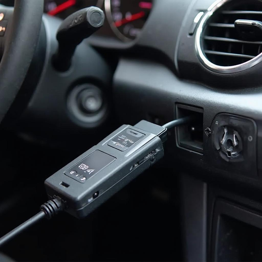
 OBD2 Scanner Connected to a Car’s OBD2 Port
Common Issues and Troubleshooting
Sometimes, even with a perfect understanding of the obd2 pin layout, you might encounter connectivity problems. Here are a few common issues:
- Loose Connection: Ensure the scanner is firmly plugged into the port.
- Bent or Damaged Pins: Inspect the pins for any physical damage.
- Blown Fuse: Check the fuse related to the OBD2 port.
For certain applications, like using the [torque obd2 vehicle profile], ensuring the correct pin configuration is critical for data accuracy. Check out [bafx products obd2 pin] for high-quality OBD2 tools.
Conclusion
The obd2 pin layout is a fundamental aspect of vehicle diagnostics. Understanding its structure and function empowers you to communicate effectively with your vehicle’s computer and unlock a wealth of information about its performance and health. This knowledge is essential for DIY mechanics and professional technicians alike.
FAQ
- How many pins are in an OBD2 connector? 16
- What does pin 16 do? It provides battery power to the OBD2 scanner.
- What is CAN communication? A high-speed communication protocol used in modern vehicles.
- Why is my scanner not connecting? Check for loose connections, damaged pins, or a blown fuse.
- Where can I find more information on OBD2? You can explore resources like [obd2 connector pin layout] for more details.
Do you have further questions about OBD2 or specific vehicle profiles? Check out our [torque obd2 vehicle profile] guide for more insights.
Contact us via WhatsApp: +1(641)206-8880, Email: [email protected] or visit our office at 789 Elm Street, San Francisco, CA 94102, USA. Our 24/7 customer support team is ready to assist you.

Leave a Reply