Your cart is currently empty!

Understanding OBD2 Wiring Diagrams (obd2 配線 図)
Understanding Obd2 配線 図 (OBD2 wiring diagrams) is crucial for anyone working with car diagnostics. Whether you’re a professional mechanic or a DIY enthusiast, knowing how to interpret these diagrams can save you time and frustration. This article provides a comprehensive guide to OBD2 wiring diagrams, explaining their importance and how to use them effectively.
What are OBD2 Wiring Diagrams (obd2 配線 図)?
OBD2 wiring diagrams, often referred to as obd2 配線 図 in Japanese, are visual representations of the electrical connections within a vehicle’s OBD2 system. They illustrate the path of each wire, the components it connects to, and the pinout configurations of the OBD2 connector itself. These diagrams are essential for troubleshooting electrical faults, installing aftermarket devices, and understanding the communication network within the vehicle.
Why are OBD2 Wiring Diagrams Important?
Having access to the correct obd2 配線 図 (OBD2 wiring diagram) is like having a roadmap for your vehicle’s electrical system. They are invaluable for:
- Troubleshooting: When a diagnostic trouble code (DTC) appears, the wiring diagram can help pinpoint the location of the fault.
- Installation: Installing aftermarket devices, such as car alarms or remote starters, requires precise wiring connections. The diagram ensures correct installation, preventing damage and ensuring proper functionality.
- Customization: Modifying your car’s electrical system, like adding additional lights or accessories, necessitates a thorough understanding of the existing wiring. The obd2 配線 図 helps avoid conflicts and ensures compatibility.
- Repair: If a wire is damaged or corroded, the diagram can guide you in replacing or repairing it correctly.
How to Read an OBD2 Wiring Diagram (obd2 配線 図)
Reading an obd2 配線 図 may seem daunting at first, but with a little practice, it becomes straightforward. Here’s a step-by-step guide:
-
Identify the OBD2 Connector: Locate the 16-pin DLC (Data Link Connector) in your vehicle. This is the point of access for the OBD2 scanner.
-
Find the Correct Diagram: Obtain the specific wiring diagram for your vehicle’s make, model, and year. Using a generic diagram can lead to errors.
-
Understand the Symbols: Familiarize yourself with the symbols used in the diagram, such as connectors, grounds, fuses, and relays.
-
Trace the Wires: Follow the path of each wire from the OBD2 connector to its corresponding component.
-
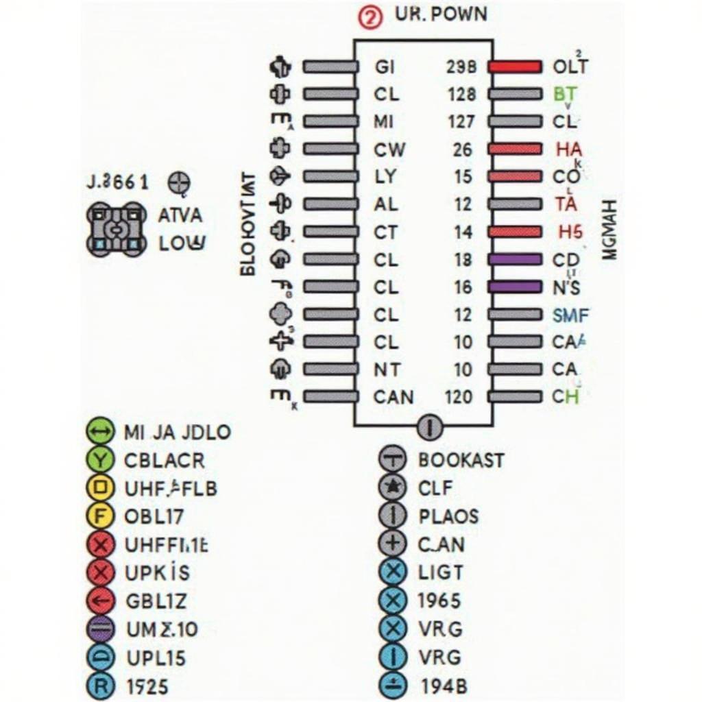
Check the Pinout: Each pin on the OBD2 connector has a specific function. The diagram will indicate which pins correspond to power, ground, communication lines, and other functions.
 OBD2 Connector Pinout Diagram
Common Uses for OBD2 Wiring Diagrams (obd2 配線 図)
Here are some common scenarios where an OBD2 wiring diagram is essential:
-
Checking for Power and Ground: If your OBD2 scanner isn’t powering on, the diagram can help you verify if the correct power and ground connections are present at the DLC.
-
Diagnosing Communication Issues: If the scanner fails to communicate with the vehicle’s ECU, the diagram can help identify potential breaks or shorts in the communication lines.
-
Installing Aftermarket Gauges: Installing aftermarket gauges often requires tapping into specific wires on the OBD2 circuit. The diagram provides the necessary information for safe and accurate connections.
“Accurate wiring diagrams are the bedrock of effective vehicle diagnostics. They empower technicians to quickly identify and resolve electrical issues, saving time and money,” says John Smith, a seasoned automotive diagnostician with over 20 years of experience.
Conclusion
Understanding obd2 配線 図 (OBD2 wiring diagrams) is an essential skill for anyone working on modern vehicles. These diagrams are invaluable for troubleshooting, installation, and customization. By following the steps outlined in this article and using the correct diagram for your vehicle, you can confidently navigate the complexities of your car’s electrical system.
FAQ
- Where can I find OBD2 wiring diagrams for my car?
- What are the common symbols used in OBD2 wiring diagrams?
- How can I tell if my OBD2 wiring diagram is correct?
- What should I do if I can’t find the specific wire I’m looking for on the diagram?
- Can I use a generic OBD2 wiring diagram for any car?
- What are the different types of OBD2 communication protocols?
- How can I tell if a wire is damaged or corroded using the diagram?
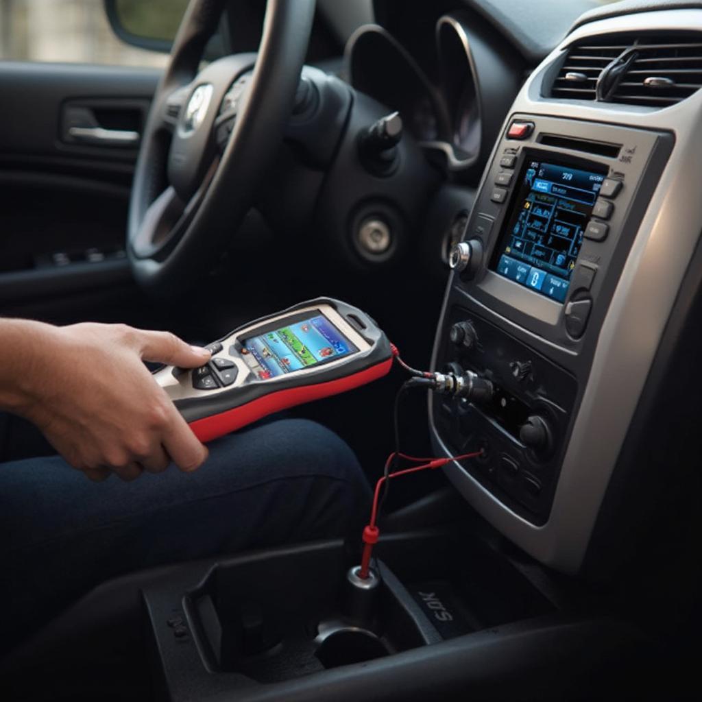
 OBD2 Scanner Connected to a Car’s DLC
Need further assistance? Contact us via WhatsApp: +1(641)206-8880, Email: [email protected] or visit us at 789 Elm Street, San Francisco, CA 94102, USA. We have a 24/7 customer support team ready to help.

Leave a Reply