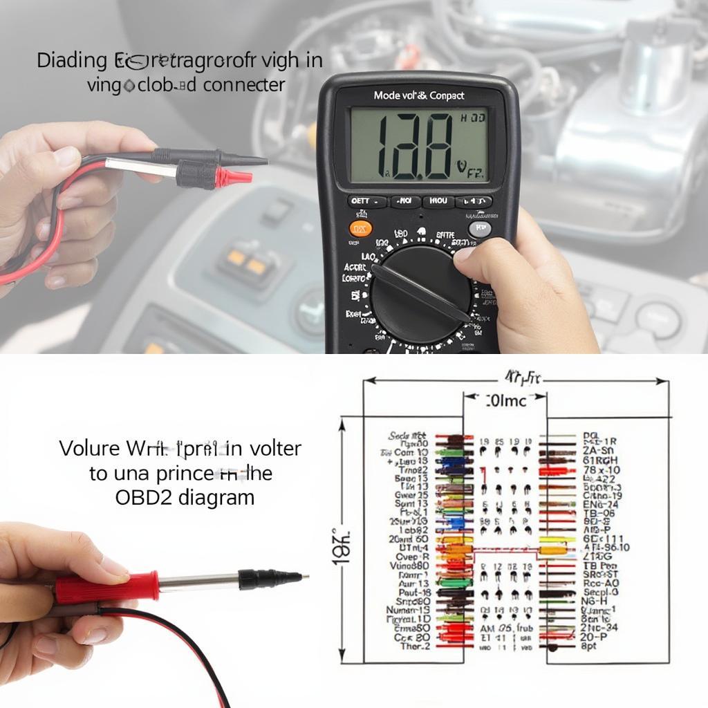
The OBD2 pinout diagram is your key to unlocking the secrets of your vehicle’s onboard diagnostic system. This guide will delve into the intricacies of the OBD2 connector, explaining its function, the meaning of each pin, and how this knowledge can empower you to diagnose and troubleshoot car problems effectively.
Decoding the OBD2 Port
The OBD2 port, typically located under the dashboard on the driver’s side, is a standardized 16-pin connector. Each pin serves a specific purpose, facilitating communication between the vehicle’s electronic control units (ECUs) and a diagnostic scanner. Understanding the rav4 2001 obd2 pinout diagram can be particularly helpful for owners of older vehicles.
What Each Pin Represents
While some pins have standardized functions, others are manufacturer-specific. Here’s a breakdown of the common pin assignments:
- Pin 1: Often used for manufacturer-specific communication.
- Pin 2: J1850 Bus+ (used by some manufacturers).
- Pin 3: Manufacturer-specific.
- Pin 4: Chassis Ground.
- Pin 5: Signal Ground.
- Pin 6: CAN High (Controller Area Network).
- Pin 7: ISO 9141-2 K-Line.
- Pin 8: Manufacturer-specific.
- Pin 9: Manufacturer-specific.
- Pin 10: J1850 Bus- (used by some manufacturers).
- Pin 11: Manufacturer-specific.
- Pin 12: Manufacturer-specific.
- Pin 13: Manufacturer-specific.
- Pin 14: CAN Low (Controller Area Network).
- Pin 15: ISO 9141-2 L-Line.
- Pin 16: Battery Power.
Understanding this pinout diagram obd2 allows you to determine which communication protocols your vehicle uses.
Why is the Pinout Diagram Important?
The pinout diagram is essential for several reasons:
- Troubleshooting: Identifying the correct pins helps pinpoint communication issues between the scanner and the vehicle’s ECUs.
- Compatibility: Ensures you’re using the correct OBD2 cable and adapter for your specific vehicle and diagnostic tool.
- Advanced Diagnostics: Knowing the pin assignments allows for more advanced diagnostics and modifications, such as directly accessing specific data streams. You can even find specific diagrams, like the 2006 mini cooper s computer pinout diagram obd2.
Utilizing the OBD2 Pinout Diagram for Diagnostics
The pinout diagram isn’t just for professionals. DIYers can also utilize this knowledge for basic troubleshooting. For instance, checking the voltage on pin 16 can confirm if the OBD2 port is receiving power. The sct x4 obd2 cable pinout wire doagra can be especially useful for those using tuning devices.
“Knowing the OBD2 pinout can save you a trip to the mechanic for simple electrical issues,” says automotive expert, David Miller. “It empowers car owners to take control of their vehicle’s diagnostics.”
 Using a Multimeter with the OBD2 Connector for Diagnostics
Different OBD2 Standards and Protocols
There are several OBD2 standards and protocols. Understanding these differences is crucial for accurate diagnostics. Knowing which pins correspond to which protocols simplifies troubleshooting. The dlc 3 obd2 to hdmi a pinout diagram is an example of a more specialized pinout.
“Different car manufacturers may use different protocols, even within the OBD2 standard,” explains automotive electronics specialist, Sarah Johnson. “Consulting the pinout diagram ensures you’re using the correct communication method.”
Conclusion
The OBD2 pinout diagram is a powerful tool for anyone working with vehicle diagnostics. Whether you’re a professional mechanic or a DIY enthusiast, understanding the function of each pin unlocks a wealth of information about your car’s health and performance. Mastering the pinout diagram obd2 allows for more informed diagnostic decisions and can even save you time and money on repairs. You can also find related information on the hdmi to dlc 3 obd2 pinout diagram.
FAQ
- What is the purpose of the OBD2 port? To provide a standardized interface for accessing vehicle diagnostic information.
- How many pins are in a standard OBD2 connector? 16
- Where is the OBD2 port usually located? Under the dashboard, typically on the driver’s side.
- Can I damage my car by using the OBD2 port? Unlikely, as long as you use compatible tools and follow proper procedures.
- What does OBD2 stand for? On-Board Diagnostics, second generation.
- Why are some pins manufacturer-specific? To allow for proprietary diagnostic functions and communication protocols.
- How can I find the specific pinout diagram for my car? Consult your vehicle’s service manual or online resources.
Need assistance? Contact us via WhatsApp: +1(641)206-8880, Email: [email protected] or visit our office at 789 Elm Street, San Francisco, CA 94102, USA. Our customer service team is available 24/7.