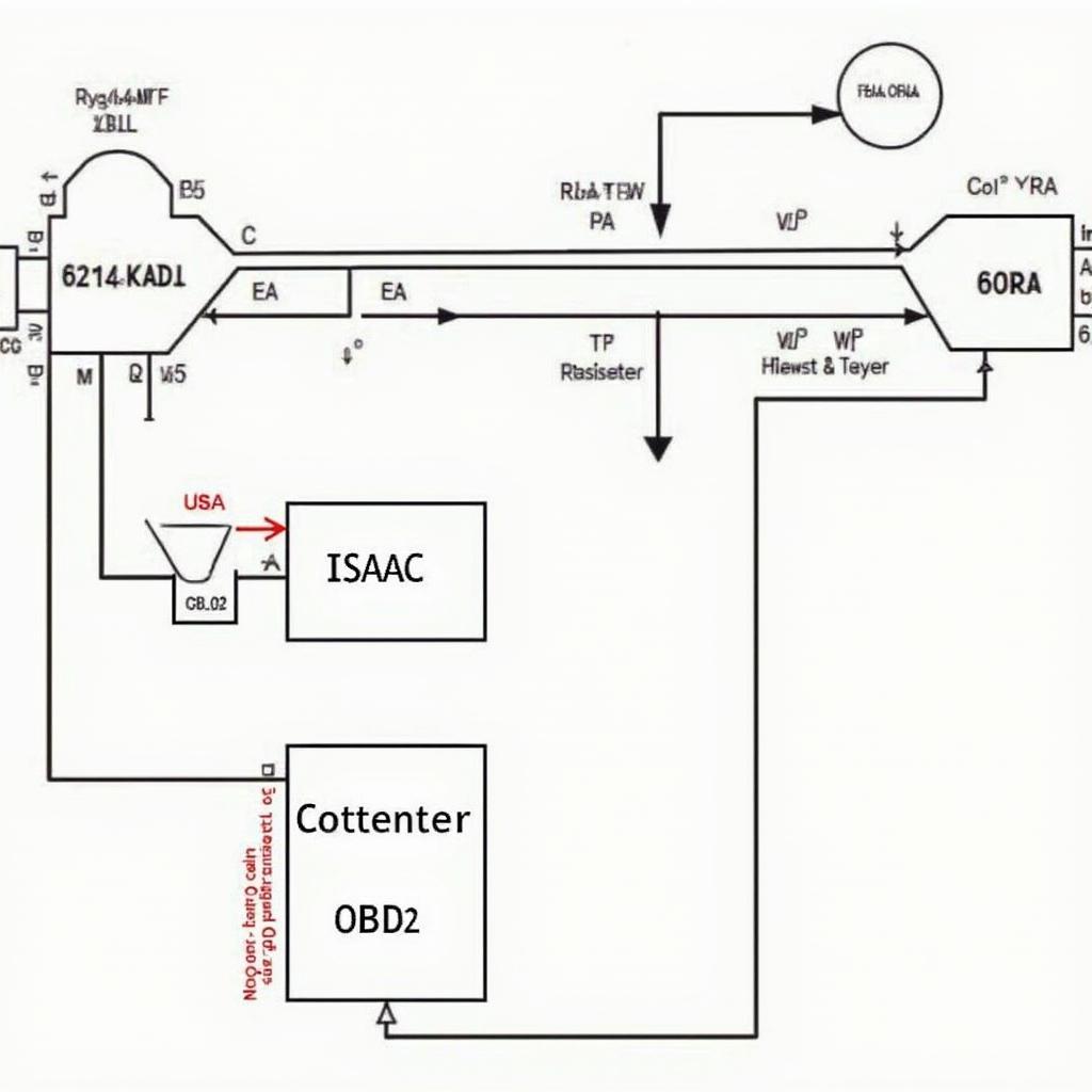
Building your own ISAAC-compatible OBD2 CAN bus PCB board can be a rewarding experience, offering a deeper understanding of vehicle diagnostics and customization options. This guide dives into the process of creating a DIY ISAAC OBD2 CAN bus PCB, covering everything from component selection to assembly and testing.
Understanding the ISAAC OBD2 CAN Bus System
Before diving into building your board, it’s crucial to grasp the fundamentals of the ISAAC platform and the OBD2 CAN bus protocol. ISAAC (Integrated System for Autonomous and Adaptive Control) provides a framework for developing autonomous vehicle applications. The OBD2 CAN bus is the communication backbone, allowing various electronic control units (ECUs) within the vehicle to exchange data. This data is crucial for diagnostics, monitoring, and control.
Planning Your DIY ISAAC OBD2 CAN Bus PCB
Careful planning is essential for a successful DIY project. Consider the specific requirements of your ISAAC application and choose components accordingly. This includes selecting the right microcontroller, CAN transceiver, OBD2 connector, and other supporting components like voltage regulators and termination resistors. A well-defined schematic is the foundation of your PCB design.
Choosing the Right Microcontroller
The microcontroller acts as the brain of your PCB, processing data and communicating with the CAN bus. Popular choices include the STM32 and ESP32 families, offering a balance of performance, features, and ease of use. Consider factors like processing power, memory, and peripheral availability when making your selection.
Selecting a CAN Transceiver
The CAN transceiver is the interface between the microcontroller and the physical CAN bus. It converts the digital signals from the microcontroller into the differential signals required for CAN communication. The MCP2551 and MCP2562 are common choices, known for their reliability and compatibility.
The OBD2 Connector and Other Components
A standard OBD2 connector is necessary to interface with the vehicle’s diagnostic port. Ensure the connector is compatible with the physical layout of your PCB. Additionally, voltage regulators provide stable power to the circuit, while termination resistors ensure signal integrity on the CAN bus.
Designing the PCB Layout
Once your schematic is finalized, you can begin designing the PCB layout. Use a PCB design software like KiCad or Eagle to create the layout. Consider factors like signal integrity, component placement, and thermal management. Proper routing of the CAN bus traces is crucial to minimize signal reflections and ensure reliable communication.
Assembling the PCB
After ordering your fabricated PCB, the next step is assembly. Soldering the components requires precision and the right tools. Start with the smallest components, like resistors and capacitors, and work your way up to larger components like the microcontroller and CAN transceiver. Use a good quality soldering iron and solder to ensure reliable connections.
Testing and Debugging
Once assembled, thoroughly test your PCB. Use a CAN bus analyzer or oscilloscope to monitor the CAN bus traffic and verify proper communication. Debugging may involve checking connections, verifying component functionality, and analyzing the code running on the microcontroller.
Conclusion
Building a DIY ISAAC OBD2 CAN bus PCB board offers a hands-on approach to understanding vehicle diagnostics and control systems. By following this guide, you can design, assemble, and test your own custom PCB, empowering you to explore the world of automotive technology. This project enhances your understanding of the ISAAC platform and the OBD2 CAN bus, paving the way for more complex automotive projects.
FAQ
- What are the advantages of building a DIY ISAAC OBD2 CAN bus PCB?
- What software can I use to design the PCB layout?
- What are some common debugging techniques for CAN bus issues?
- Where can I find resources for learning more about the ISAAC platform?
- What are the safety precautions I should take when working with vehicle electronics?
- What type of microcontroller is recommended for this project?
- How can I ensure signal integrity on the CAN bus?
Please contact us via WhatsApp: +1(641)206-8880, Email: [email protected] or visit our office at 789 Elm Street, San Francisco, CA 94102, USA for any assistance. Our 24/7 customer support team is ready to help.
