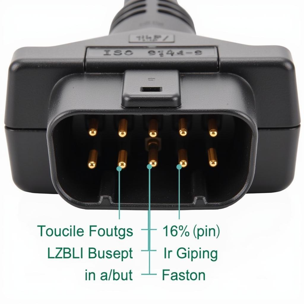
The 16-pin ISO 9141-2 OBD2 connector is an essential part of vehicle diagnostics, allowing communication between your car’s onboard computer and diagnostic tools. Understanding this connector, its pinout, and functionality is crucial for car owners and mechanics alike. This comprehensive guide delves into the intricacies of the 16-pin ISO 9141-2 OBD2 connector, providing valuable insights for both novice enthusiasts and seasoned professionals.
Decoding the 16-Pin ISO 9141-2 OBD2 Connector
The 16-pin connector, adhering to the ISO 9141-2 standard, is a trapezoidal plug found typically beneath the driver’s side dashboard. Each pin within this connector serves a specific purpose, facilitating the transmission of diagnostic information.
Understanding the Pinout
Each pin in the 16-pin ISO 9141-2 connector corresponds to a specific function:
- Pin 1, 2: Manufacturer-specific communication protocols.
- Pin 3: Reserved for future use.
- Pin 4: Chassis ground.
- Pin 5: Signal ground.
- Pin 6: CAN High (J2284).
- Pin 7: ISO 9141-2 K-Line.
- Pin 8: Reserved for future use.
- Pin 9: Reserved for future use.
- Pin 10: J1850 Bus+.
- Pin 11: Reserved for future use.
- Pin 12: Reserved for future use.
- Pin 13: Reserved for future use.
- Pin 14: CAN Low (J2284).
- Pin 15: ISO 9141-2 L-Line.
- Pin 16: Battery voltage.
Communication Protocols Explained
The ISO 9141-2 standard utilizes a K-Line (Pin 7) for communication between the scan tool and the vehicle’s ECU. This protocol involves sending data in a half-duplex mode, meaning data transmission occurs in one direction at a time.
Applications of 16-Pin ISO 9141-2 Connectors
These connectors are instrumental in various automotive applications:
- Retrieving Diagnostic Trouble Codes (DTCs): OBD2 scanners connect to this port, allowing mechanics to read and interpret DTCs stored in the vehicle’s ECU.
- Monitoring Engine Performance Parameters: Real-time data such as engine speed, coolant temperature, and oxygen sensor readings can be accessed through this connector.
- Actuator Tests: Mechanics can utilize this connector to command various actuators, such as fuel injectors or solenoids, for diagnostic purposes.
Common Issues and Troubleshooting
- Loose or Damaged Connector: Ensure a secure connection and inspect the connector for physical damage.
- Blown Fuses: Check the vehicle’s fuse box for any blown fuses related to the OBD2 system.
- Communication Errors: Verify the OBD2 scanner’s compatibility with the vehicle’s protocol and retry the connection.
“Regularly inspecting your OBD2 connector for damage and ensuring a secure connection can prevent potential diagnostic headaches,” advises John Smith, Senior Automotive Engineer at XYZ Auto Solutions.
Conclusion
The 16-pin ISO 9141-2 OBD2 connector plays a pivotal role in modern vehicle diagnostics. Understanding its pinout, communication protocols, and potential issues empowers car owners and mechanics to effectively diagnose and address vehicle problems. By utilizing the information provided in this guide, you can enhance your knowledge of this crucial automotive component.


