The transition from OBD1 to OBD2 (On-Board Diagnostics) systems in the early to mid-1990s brought significant changes to automotive diagnostics, including the way distributors are wired. While OBD1 systems relied on relatively simple distributor setups, OBD2 introduced more complex electronic controls and sensors. Understanding the differences in the distributor wiring diagrams between these two systems is crucial for anyone working on older vehicles.
This article delves into the intricacies of OBD1 and OBD2 distributor wiring diagrams, providing valuable insights for enthusiasts and mechanics alike.
Decoding the OBD1 Distributor Wiring Diagram
OBD1 systems, prevalent in vehicles manufactured before 1996, utilized distributors with a relatively straightforward wiring configuration. The distributor played a crucial role in both ignition timing and fuel delivery.
A typical OBD1 distributor housed a mechanical ignition pickup (often a Hall effect sensor) that sent signals to the Electronic Control Unit (ECU). These signals informed the ECU about the engine’s position, allowing it to manage ignition timing and fuel injection.
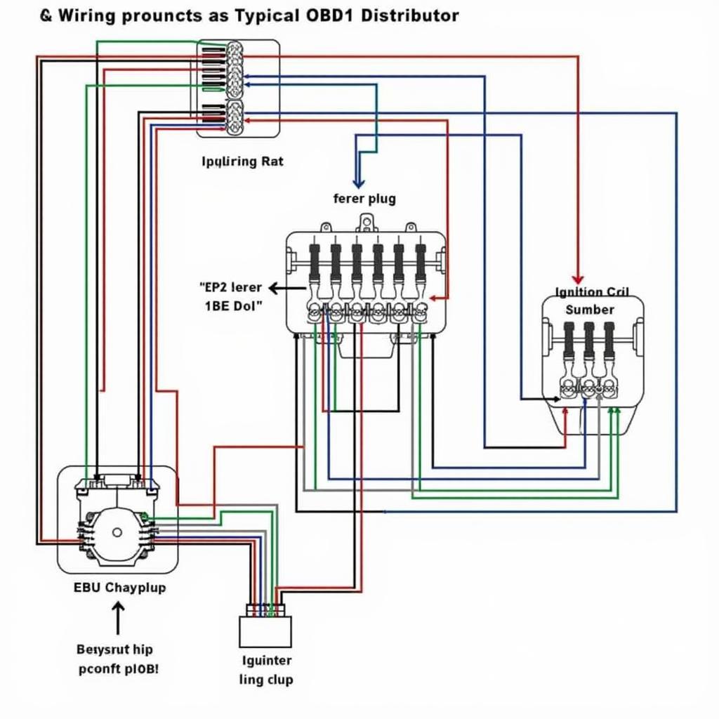
 OBD1 Distributor Wiring Diagram
The wiring diagram for an OBD1 distributor usually includes connections for:
- Battery Positive (+): Provides power to the distributor.
- Ignition Switch: Activates the ignition system when the key is turned.
- Ignition Coil: Receives the high-voltage signal from the distributor to generate spark.
- Ignition Module: Works in conjunction with the distributor pickup to control spark timing.
- ECU: Processes signals from the distributor to adjust ignition timing and fuel delivery.
Navigating the OBD2 Distributor Wiring Diagram
OBD2 systems, mandated in the United States for vehicles manufactured from 1996 onwards, introduced more sophisticated electronic engine management. This shift towards greater electronic control led to changes in the distributor’s role and its corresponding wiring.
While some OBD2 vehicles retained distributors, their function shifted primarily to ignition timing. The ECU took over control of fuel delivery, often eliminating the need for a mechanical fuel injection pump.
In OBD2 systems, the distributor wiring diagram typically involves connections to:
- Crankshaft Position Sensor (CKP): Provides the ECU with precise information about crankshaft position and speed.
- Camshaft Position Sensor (CMP): Relays camshaft position to the ECU for optimal ignition timing and fuel synchronization.
- ECU: Processes signals from various sensors, including the CKP and CMP, to control ignition timing, fuel injection, and other engine parameters.
Key Differences and Considerations
The transition from OBD1 to OBD2 brought about several key differences in distributor wiring:
- Increased Electronic Control: OBD2 systems rely heavily on electronic sensors and actuators, minimizing the mechanical components within the distributor.
- Focus on Diagnostics: OBD2 introduced standardized diagnostic trouble codes (DTCs) and a universal connector to facilitate easier troubleshooting.
- Emissions Control: OBD2 regulations emphasized stricter emissions control, leading to more precise ignition timing and fuel delivery management.
When working with vehicles equipped with distributors, understanding these differences is paramount for accurate diagnosis and repair. Consulting factory wiring diagrams specific to the vehicle’s make, model, and year is crucial, as variations exist between manufacturers and even specific models.
“The shift to OBD2 marked a turning point in automotive diagnostics,” says John Anderson, a veteran automotive engineer with over 20 years of experience. “Understanding the nuances of both OBD1 and OBD2 distributor wiring is essential for anyone working on a diverse range of vehicles.”
Conclusion
Navigating the intricacies of OBD1 and OBD2 distributor wiring diagrams can be complex, but it’s an essential skill for automotive enthusiasts and professionals alike. While OBD1 systems featured simpler setups, OBD2 brought more advanced electronic controls and a greater emphasis on diagnostics.
By understanding the key differences between these systems and referring to specific vehicle wiring diagrams, you can confidently tackle distributor-related issues and keep those engines running smoothly.

