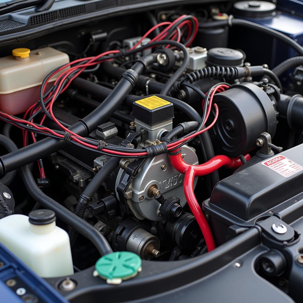
Understanding your car’s wiring harness can seem daunting, especially when it comes to performance-oriented vehicles like the Acura Integra GSR. The GSR’s engine, known for its high-revving nature, relies heavily on a precisely calibrated electrical system. At the heart of this system lies the OBD2 GSR wiring harness, a complex network of wires and connectors responsible for seamless communication between various sensors, actuators, and the ECU (Engine Control Unit).
Why Understanding Your OBD2 GSR Wiring Harness Matters
Whether you’re troubleshooting engine issues, installing aftermarket performance parts, or simply curious about your car’s inner workings, having a grasp of the OBD2 GSR wiring harness diagram is crucial. It serves as a roadmap, allowing you to:
- Diagnose Electrical Problems: A faulty wiring harness can lead to a variety of issues, from misfiring cylinders to a complete engine stall. The wiring diagram helps you trace circuits and identify potential problem areas.
- Install Aftermarket Components: Many performance upgrades, like upgraded ECUs or performance sensors, require splicing into the existing wiring harness. The diagram ensures correct connections and avoids costly mistakes.
- Perform Engine Swaps: Swapping a B18C1 engine (found in the GSR) into another vehicle requires meticulous wiring adaptation. The wiring diagram becomes your bible, guiding you through merging two different electrical systems.
Navigating the OBD2 GSR Wiring Harness Diagram
While the sight of a wiring diagram can be intimidating, breaking it down into manageable sections makes it less overwhelming. Here’s a step-by-step approach:
- Locate the Legend: Every wiring diagram includes a legend that deciphers the symbols, abbreviations, and color codes used. Familiarize yourself with it before proceeding.
- Identify Key Components: Locate the ECU, sensors (e.g., crankshaft position sensor, oxygen sensor), actuators (e.g., fuel injectors, ignition coils), and grounds on the diagram.
- Trace Circuits: Follow the lines (representing wires) from the ECU to various components. The color codes on the lines correspond to wire colors in the actual harness.
- Pinpoint Connectors: Connectors are represented by shapes on the diagram, each with numbered pins. These numbers are crucial when testing circuits or splicing wires.
Common Issues and Troubleshooting Tips
- Damaged Wires: Over time, heat, vibration, and exposure to fluids can damage wires, leading to shorts or open circuits. Visual inspection and multimeter testing can help identify faulty wires.
- Loose Connections: A loose connection at a connector can disrupt communication within the harness. Make sure all connectors are securely fastened.
- Blown Fuses: Fuses protect the harness from overloads. A blown fuse often points to a short circuit somewhere in the system. Consult the owner’s manual for fuse locations and ratings.
Expert Insights
“When working with any wiring harness, but especially one as intricate as the GSR’s, patience and meticulousness are key. Always disconnect the battery before working on the harness, and triple-check your connections before reconnecting the battery.” – John S., ASE Certified Master Technician
Conclusion
The OBD2 GSR wiring harness is the nervous system of your high-performance engine. Understanding its layout and function is essential for anyone looking to diagnose problems, install upgrades, or simply appreciate the complexity of automotive engineering. Remember, a well-maintained wiring harness ensures optimal performance and reliability for your Acura Integra GSR.


