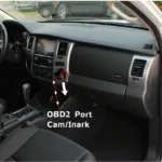
Building an Arduino CAN bus ECU OBD2 simulator offers a powerful way to understand and interact with your vehicle’s electronic systems. This approach allows for testing, diagnostics, and even custom functionality implementation without risking damage to your car’s actual ECU. Whether you’re a professional mechanic, a hobbyist, or just curious about car electronics, this guide will cover everything you need to know about creating your own simulator.
Understanding the Components: Arduino, CAN Bus, ECU, and OBD2
Before diving into the construction, it’s crucial to grasp the roles of each component. The Arduino acts as the brain of our simulator, executing the programmed logic. The Controller Area Network (CAN bus) is the communication highway within the vehicle, allowing various modules to exchange data. The Engine Control Unit (ECU) manages the engine’s performance based on sensor inputs. Lastly, the On-Board Diagnostics II (OBD2) port provides a standardized interface to access and interpret vehicle data.
An Arduino OBD2 CAN bus setup empowers you to simulate specific ECU behaviors. This capability is invaluable for testing diagnostic tools and experimenting with various scenarios. [arduino obd2 scanner] provides more detail on how an Arduino can interact with your vehicle’s OBD2 system.
The Importance of CAN Bus Communication
The CAN bus is the backbone of modern vehicle communication. It allows different modules, such as the ECU, transmission control unit (TCU), and ABS module, to communicate with each other efficiently and reliably. Understanding how the CAN bus works is fundamental to creating an effective OBD2 simulator.
What if you could test your new diagnostic tool without connecting it to your car? An [obd2 monitor simulator] allows you to do just that, providing a safe and controlled environment for experimentation.
Building Your Arduino CAN Bus ECU OBD2 Simulator
Let’s break down the process into manageable steps.
-
Gather the necessary components: You’ll need an Arduino board (Uno, Mega, or Nano), a CAN bus transceiver (MCP2515 is a popular choice), an OBD2 connector, jumper wires, and a breadboard.
-
Connect the hardware: Wire the CAN transceiver to the Arduino and connect the OBD2 connector to the transceiver.
-
Install the necessary libraries: The MCP_CAN library is commonly used for interfacing with the MCP2515 transceiver.
-
Write the code: The code will define the simulated ECU behavior, including the responses to OBD2 requests.
More in-depth information on connecting your Arduino to the CAN bus can be found at [arduino obd2 can bus].
Programming Your Simulator
The programming stage is where you define the functionality of your simulator. You can program it to respond to specific OBD2 PIDs (Parameter IDs) with predefined values, simulate fault codes, or even generate synthetic sensor data.
“Simulating specific fault codes is a powerful way to test diagnostic tools and procedures without needing access to a vehicle with those actual faults,” says Alex Martinez, Senior Automotive Engineer at Apex Automotive Solutions.
Testing and Debugging Your Simulator
Once the hardware and software are in place, it’s time to test your creation. Use an OBD2 scanner to connect to your simulator and observe the responses. Debug any issues you encounter and refine your code.
Common Troubleshooting Tips
- Double-check your wiring connections.
- Verify that the correct libraries are installed.
- Carefully examine your code for errors.
“A common mistake is forgetting to terminate the CAN bus properly. This can lead to communication errors and unreliable performance,” advises Maria Garcia, Embedded Systems Engineer at FutureTech Automotive.
Conclusion: Empowering Automotive Exploration with Arduino
Building an arduino can bus ecu obd2 simulator opens a world of possibilities for automotive enthusiasts and professionals alike. It’s a practical and engaging way to delve into the intricacies of vehicle electronics, enhance diagnostic skills, and explore custom solutions. This guide has equipped you with the fundamental knowledge and steps to embark on this exciting journey.
FAQ
-
What type of Arduino is best for this project?
Any Arduino with sufficient memory and processing power will work, such as the Uno, Mega, or Nano. -
Where can I find OBD2 PID information?
Various online resources and automotive documentation provide comprehensive lists of OBD2 PIDs. -
Can I simulate real-world driving scenarios?
Yes, you can program your simulator to generate data that mimics real-world driving conditions.
Common Scenarios and Questions:
- Scenario: I’m trying to simulate a specific fault code, but my scanner isn’t showing it.
- Possible Solution: Verify that the fault code is being sent on the correct CAN ID and that your scanner is configured to receive messages on that ID.
Further Exploration
Explore more OBD2 projects with Arduino by visiting our website.
Need Help?
Contact us via WhatsApp: +1(641)206-8880, Email: [email protected] or visit us at 789 Elm Street, San Francisco, CA 94102, USA. Our 24/7 customer support team is ready to assist you.

