The autocom obd2 pinout is essential for anyone working with vehicle diagnostics. Understanding this layout allows you to effectively utilize your OBD2 scanner, providing valuable insights into your car’s performance and potential issues. This article will delve deep into the specifics of the autocom obd2 pinout, offering a comprehensive guide to its functionality and applications.
Decoding the Autocom OBD2 Pinout
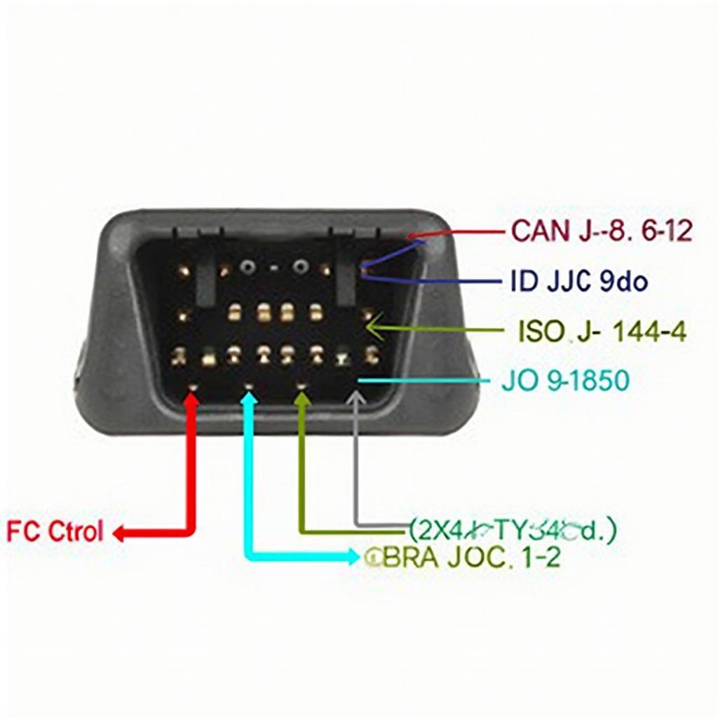
The OBD2 connector, a standardized 16-pin interface, serves as the gateway to your vehicle’s diagnostic system. Each pin within the autocom obd2 pinout has a specific function, ranging from power supply to communication lines. Knowing the purpose of each pin is crucial for troubleshooting and advanced diagnostics.
Power and Ground Pins in Autocom OBD2
Pins 4 and 5 of the autocom obd2 pinout are dedicated to chassis ground and signal ground, respectively, ensuring a stable electrical reference for accurate data transmission. Pin 16 supplies battery power, enabling the OBD2 scanner to operate independently.
Communication Protocols: CAN, J1850, and ISO 9141
The autocom obd2 pinout supports various communication protocols, including CAN (Controller Area Network), J1850 (PWM and VPW), and ISO 9141-2. Pins 2 and 10 are dedicated to J1850 bus+, and bus- respectively, while pins 6 and 14 handle CAN high and CAN low communication. Pin 7 is designated for ISO 9141-2 K-line communication.
Other Important Pins on the Autocom OBD2 Connector
Beyond power and communication, the autocom obd2 pinout includes pins for specific diagnostic functions. Pin 1 provides access to the manufacturer-specific diagnostic link, while pin 9 facilitates communication with the vehicle’s OBD2 system.
Using the Autocom OBD2 Pinout for Diagnostics
Understanding the autocom obd2 pinout allows for more than just reading error codes. It empowers users to monitor real-time data, perform advanced diagnostics, and even program certain vehicle modules.
Troubleshooting with the Autocom OBD2 Pinout
When faced with a “check engine” light, knowing the autocom obd2 pinout can help pinpoint the source of the problem. By connecting an OBD2 scanner and interpreting the data from specific pins, you can identify faulty sensors or malfunctioning systems.
Advanced Diagnostics with Autocom OBD2
For experienced technicians, the autocom obd2 pinout opens doors to advanced diagnostic procedures. By accessing specific pins, you can perform bi-directional control tests, monitor sensor data streams, and gain a deeper understanding of the vehicle’s performance.
Conclusion: Mastering the Autocom OBD2 Pinout
Mastering the autocom obd2 pinout is fundamental for effective vehicle diagnostics. Whether you’re a DIY enthusiast or a professional technician, understanding this layout empowers you to unlock valuable insights into your car’s performance and address potential issues proactively.
FAQ
- What is the purpose of pin 16 on the autocom obd2 pinout? (Battery Power)
- Which pins are used for CAN communication? (6 and 14)
- What is the role of the ground pins in the autocom obd2 pinout? (Provide a stable electrical reference)
- How can understanding the autocom obd2 pinout help with troubleshooting? (Identify faulty sensors and systems)
- What are some of the communication protocols supported by the autocom obd2 pinout? (CAN, J1850, ISO 9141-2)
- What is the function of pin 9 on the autocom obd2 pinout? (OBD2 system communication)
- Where can I find a detailed diagram of the autocom obd2 pinout? (Refer to the images in this article and manufacturer’s documentation)
Need assistance? Contact us via WhatsApp: +1(641)206-8880, Email: [email protected] or visit us at 789 Elm Street, San Francisco, CA 94102, USA. We have a 24/7 customer support team.


