
Your cart is currently empty!
How to Make an OBD2 to USB Cable (Como Hacer un Cable OBD2 a USB)
Creating your own OBD2 to USB cable can be a rewarding project, especially if you’re looking for a customized or cost-effective solution for connecting your vehicle’s diagnostic port to your computer. This guide will cover the essentials of making an OBD2 to USB cable (Como Hacer Un Cable Obd2 A Usb), from the components you need to the steps involved in assembling it.
Understanding the OBD2 Standard and USB Interface
The OBD2 (On-Board Diagnostics II) standard is a universal system used in vehicles to diagnose and monitor engine performance. Connecting to this system through a USB interface allows you to access real-time data, diagnose trouble codes, and even perform some modifications using dedicated software. Understanding both OBD2 and USB is crucial for building a successful cable. USB provides the communication pathway between your computer and the vehicle’s OBD2 port.
Gathering the Necessary Components for Your OBD2 to USB Cable
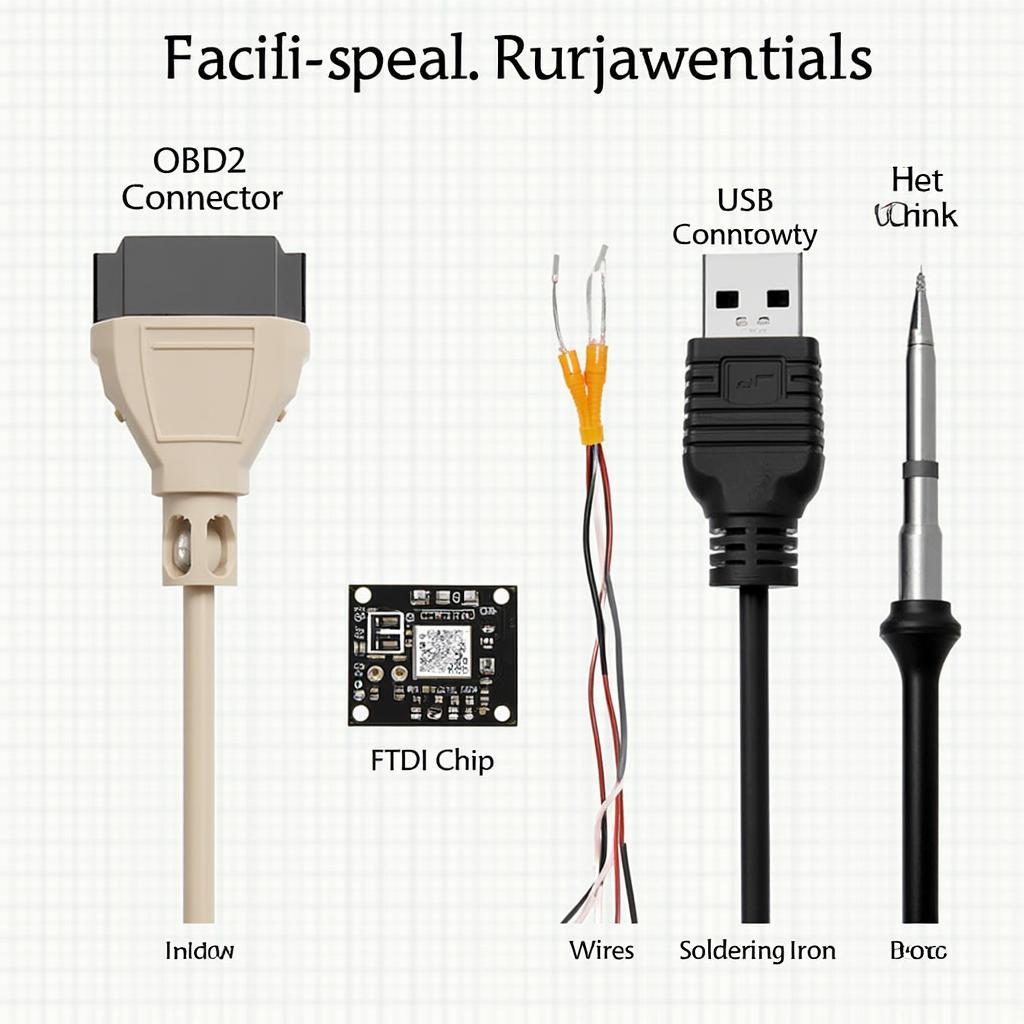
Before you begin assembling your cable, you’ll need the following components:
- OBD2 connector: A male OBD2 connector is essential for plugging into your vehicle’s diagnostic port.
- USB connector: A male USB connector (Type A) will connect to your computer.
- FTDI chip: An FTDI (Future Technology Devices International) chip is the heart of the conversion process, translating signals between OBD2 and USB protocols. The FT232RL is a popular choice for this project.
- Wires and cables: You’ll need wires to connect the various components. Ensure they are appropriately gauge for carrying the data signals.
- Soldering iron and solder: These are crucial for creating strong and reliable connections between components.
- Heat shrink tubing: This helps to insulate the soldered connections and provide a professional finish.
- Enclosure (optional): A plastic enclosure can protect the electronics and provide a more finished look.
Step-by-Step Guide to Assembling Your OBD2 to USB Cable
Follow these steps carefully to assemble your cable:
- Identify the pinout of the OBD2 and USB connectors: Consult the datasheets for both connectors to identify the correct pin assignments.
- Connect the FTDI chip to the USB connector: Solder the appropriate wires from the FTDI chip to the USB connector pins. Refer to the FTDI datasheet for precise instructions.
- Connect the FTDI chip to the OBD2 connector: Similarly, solder the appropriate wires from the FTDI chip to the OBD2 connector pins, following the pinout diagram.
- Insulate the connections: Use heat shrink tubing to cover all soldered connections.
- Test the connection: Connect the assembled cable to your vehicle and computer. Use OBD2 software to verify that the connection is successful.
OBD2 to USB Cable Components
After connecting the FTDI chip, double-check all connections before proceeding.
Troubleshooting Common Issues
Sometimes, the cable might not work as expected. Here are some common issues and their solutions:
- No communication: Verify the driver installation for the FTDI chip on your computer. Ensure the correct COM port is selected in your OBD2 software.
- Intermittent connection: Check for loose or poorly soldered connections.
- Incorrect data: Double-check the wiring and pin assignments.
Careful soldering is key to a reliable connection.
Advanced Considerations and Customization Options
Once you’re comfortable with the basic build, you can consider adding features like:
- A switch for selecting different CAN protocols: This is particularly useful for working with vehicles that utilize different CAN standards.
- LED indicators for power and data transfer: These can help visually confirm the cable’s status.
Adding an enclosure provides a professional finish and protects the electronics.
“Building your own OBD2 cable gives you complete control over its functionality,” says automotive electronics expert, Dr. Robert Hernandez. “You can tailor it to your specific needs and ensure compatibility with your vehicle and diagnostic software.”
Building an OBD2 to USB cable (como hacer un cable obd2 a usb) is a manageable project for those with basic soldering skills. It offers a cost-effective way to interface with your vehicle’s diagnostics. This guide provides the essential steps for creating a functional and reliable cable.
“Understanding the pinouts is absolutely critical. A single misplaced wire can lead to communication errors or even damage to the vehicle’s systems,” cautions automotive engineer, Susan Lee.
In conclusion, creating an OBD2 to USB cable allows for customized and cost-effective vehicle diagnostics. By following this guide, you can successfully build your own cable and unlock the power of OBD2 data.
FAQ
- What type of FTDI chip should I use? The FT232RL is recommended.
- Where can I find the OBD2 connector pinout? Refer to the OBD2 standard documentation or search online.
- What software can I use with my OBD2 to USB cable? Various OBD2 software options are available, depending on your operating system and specific needs.
- Can I damage my car by making a mistake? Yes, incorrect wiring can potentially damage the vehicle’s systems. Double-check all connections.
- What gauge wire should I use? 22-24 AWG is generally suitable.
- Do I need an enclosure for the cable? It’s optional but recommended for protection.
- Where can I find drivers for the FTDI chip? On the FTDI website.
Need further assistance? Contact us via WhatsApp: +1(641)206-8880, Email: [email protected] or visit us at 789 Elm Street, San Francisco, CA 94102, USA. Our 24/7 customer support team is ready to help.
Leave a Reply