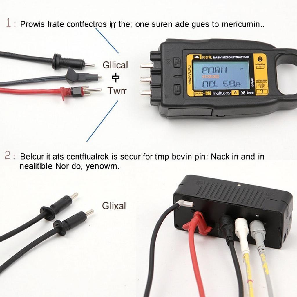
Understanding the diagram of OBD2 connector wire colors is crucial for anyone working with car diagnostics. Whether you’re a professional mechanic or a DIY enthusiast, knowing which wire corresponds to which function can save you time and frustration. This guide will delve into the intricacies of OBD2 connector wire colors, providing a clear and comprehensive understanding of this essential diagnostic interface.
The OBD2 (On-Board Diagnostics II) system is a standardized system that allows you to access diagnostic information from your vehicle’s computer. The system uses a 16-pin connector, and each pin is assigned a specific function, identified by a unique wire color. Knowing these colors is key to troubleshooting car problems effectively. You can check the obd2 wiring diagram for more information.
Decoding the OBD2 Connector Wire Colors
The OBD2 connector, typically located under the driver-side dashboard, houses 16 pins, each with a designated wire color. These colors are standardized across most vehicles, ensuring consistency in diagnostics. Let’s break down the color codes and their corresponding functions:
- Pin 1 (Manufacturer Discretionary): This pin’s function and color vary by manufacturer.
- Pin 2 (J1850 Bus+): Often found with a white/orange stripe and used for communication on the J1850 bus, primarily in Ford vehicles.
- Pin 3 (Manufacturer Discretionary): Similar to pin 1, this pin’s function and color vary by manufacturer.
- Pin 4 (Chassis Ground): Typically black, this pin provides the ground connection for the OBD2 system.
- Pin 5 (Signal Ground): Commonly gray, this pin provides a ground reference for sensor signals.
- Pin 6 (CAN High (J-2284)): Usually orange, this pin carries the high-speed CAN bus communication signals.
- Pin 7 (K-Line ISO 9141-2): Often white, this pin is used for communication on the K-Line protocol, prevalent in many European and Asian vehicles.
- Pin 8 (Manufacturer Discretionary): Another manufacturer-specific pin.
- Pin 9 (Manufacturer Discretionary): Also manufacturer-specific.
- Pin 10 (J1850 Bus-): Typically black/yellow stripe and used for communication on the J1850 bus, primarily in GM vehicles.
- Pin 11 (Manufacturer Discretionary): Manufacturer-specific function and color.
- Pin 12 (Manufacturer Discretionary): Manufacturer-specific function and color.
- Pin 13 (Manufacturer Discretionary): Manufacturer-specific function and color.
- Pin 14 (CAN Low (J-2284)): Usually green, this pin carries the low-speed CAN bus communication signals.
- Pin 15 (L-Line ISO 9141-2): Often purple, this pin is used for communication on the L-Line protocol.
- Pin 16 (Battery Power): Always red, this pin provides power to the OBD2 system directly from the vehicle’s battery.
For a deeper dive into OBD2 wiring schematics, check out this resource: obd2 wiring schematic.
Why is Knowing OBD2 Wire Colors Important?
Understanding OBD2 wire colors is fundamental for several reasons:
- Troubleshooting: Identifying broken or shorted wires can be significantly easier if you know the correct color codes.
- DIY Repairs: For those who prefer to handle car maintenance themselves, knowing the wire colors can be invaluable when installing or repairing OBD2 related components.
- Advanced Diagnostics: Understanding the different communication protocols (CAN, J1850, ISO 9141-2) and their corresponding wire colors allows for more in-depth diagnostics.
- Custom Installations: When adding aftermarket accessories that interface with the OBD2 system, knowing the wire colors is essential for proper connection.
“Knowing your OBD2 wire colors is like having a roadmap to your car’s brain,” says Alex Thompson, a seasoned automotive diagnostic technician. “It allows you to pinpoint issues quickly and efficiently.”
Common OBD2 Wire Color Issues and Solutions
Sometimes, you might encounter issues related to OBD2 wire colors:
-
Faded or Damaged Wires: Over time, wires can become faded or damaged, making it difficult to identify their colors. A simple solution is to use a multimeter to check the continuity of each wire and identify its corresponding pin. For more information about OBD2 pinouts and their colors, you can visit obd2 pinout color.
-
Non-Standard Wire Colors: While rare, some vehicles may use non-standard wire colors. In such cases, consulting the vehicle’s service manual is crucial.
 Testing OBD2 Connector with Multimeter
Conclusion
Understanding the diagram obd2 connector wire colors is paramount for effective vehicle diagnostics. This knowledge empowers both professionals and DIY enthusiasts to troubleshoot issues, perform repairs, and gain deeper insights into their vehicles’ inner workings. By familiarizing yourself with the color codes and their corresponding functions, you’ll be well-equipped to navigate the complexities of the OBD2 system. For those interested in specific vehicle wiring, the primary 02 sensor wiring obd2 civic and h22 obd1 to obd2 distributor wiring resources can provide valuable information.
FAQ
-
What does OBD2 stand for?
- OBD2 stands for On-Board Diagnostics II.
-
Where is the OBD2 connector located?
- It’s usually located under the driver-side dashboard.
-
Are OBD2 wire colors standardized?
- Yes, they are standardized across most vehicles.
-
What is the purpose of the CAN bus wires?
- They carry high-speed communication signals.
-
What should I do if my car uses non-standard wire colors?
- Consult your vehicle’s service manual.
-
Why is Pin 16 always red?
- It carries battery power to the OBD2 system.
- What is the function of Pin 4?
- It provides the chassis ground connection.
Have any other questions regarding your car’s OBD2 system? Check out these helpful resources:
- OBD2 Connector Wiring Diagrams
- OBD2 Pinout Information
- OBD2 Troubleshooting Guides
Need assistance with your vehicle diagnostics? Contact us via WhatsApp: +1(641)206-8880, Email: [email protected], or visit us at 789 Elm Street, San Francisco, CA 94102, USA. Our 24/7 customer support team is ready to help.

