The 14-pin OBD2 scanner diagram is essential for anyone working with vehicle diagnostics. Understanding its layout and pin functions allows for effective troubleshooting and repair. This article will delve into the details of the OBD2 connector, explaining the purpose of each pin and providing valuable insights for both professionals and DIY enthusiasts.
Decoding the 14-Pin OBD2 Connector
The OBD2 connector, a standardized interface, is the gateway to a vehicle’s diagnostic system. This 14-pin connector, typically located under the dashboard on the driver’s side, allows you to connect an OBD2 scanner to retrieve diagnostic trouble codes (DTCs), monitor vehicle performance, and access a wealth of other information.
Pin-by-Pin Breakdown of the OBD2 Diagram
Each pin on the OBD2 connector has a specific function, allowing communication between the scanner and the vehicle’s various control modules. Let’s examine each pin in detail:
- Pin 1: Not used in most applications.
- Pin 2: J1850 Bus+ (used by some Chrysler, Ford, and GM vehicles).
- Pin 3: Not used in most applications.
- Pin 4: Chassis Ground.
- Pin 5: Signal Ground.
- Pin 6: CAN High (Controller Area Network).
- Pin 7: K-Line (ISO 9141-2 and ISO 14230-4).
- Pin 8: Not used in most applications.
- Pin 9: Not used in most applications.
- Pin 10: J1850 Bus- (used by some Chrysler, Ford, and GM vehicles).
- Pin 11: Not used in most applications.
- Pin 12: Not used in most applications.
- Pin 13: Not used in most applications.
- Pin 14: Battery Power (12V).
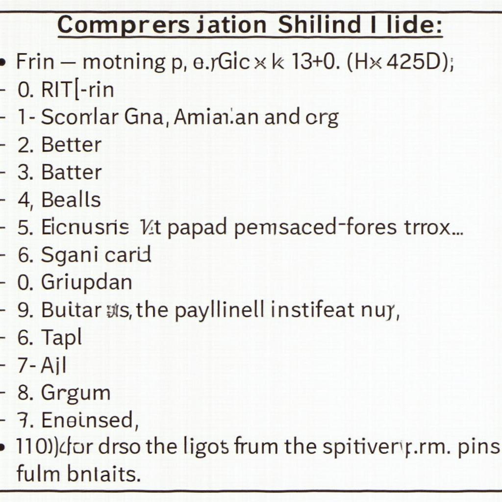
 A chart detailing the function of each pin on the OBD2 connector.
Understanding these pin functions is crucial for using an OBD2 scanner effectively and interpreting the data retrieved. For example, knowing the difference between Chassis Ground (Pin 4) and Signal Ground (Pin 5) can help prevent misdiagnosis.
Why is the OBD2 Scanner Diagram Important?
The diagram provides a clear visual representation of the connector, enabling users to correctly identify each pin and its function. This is crucial for several reasons:
- Troubleshooting: Correctly identifying pins helps diagnose communication issues between the scanner and the vehicle.
- DIY Repairs: Understanding the diagram empowers vehicle owners to perform basic diagnostics and repairs themselves. obd2 cable diagram
- Advanced Diagnostics: For professionals, knowing the pinout is essential for advanced diagnostics and troubleshooting.
“Understanding the OBD2 pinout is like knowing the language your car speaks,” says automotive expert, David Miller. “It’s the key to unlocking valuable information about your vehicle’s health and performance.”
Common Questions About the 14-Pin OBD2 Scanner Diagram
What if my car doesn’t have a 14-pin connector? Some older vehicles may use different connectors. Consult your vehicle’s service manual for specific information.
How can I test the pins on my OBD2 connector? A multimeter can be used to test for voltage and ground.
Can I damage my car by using an OBD2 scanner incorrectly? While unlikely, incorrect usage can potentially cause issues. Always ensure you are using a compatible scanner and following the correct procedures. obd2 cable diagram
Conclusion
The 14-pin OBD2 scanner diagram is an essential tool for understanding your vehicle’s diagnostic system. By understanding each pin’s function, you can unlock valuable information for troubleshooting and repair. This knowledge empowers both DIY enthusiasts and professionals to effectively diagnose and maintain their vehicles.
For further assistance, please contact us via WhatsApp: +1(641)206-8880, Email: [email protected], or visit our office at 789 Elm Street, San Francisco, CA 94102, USA. Our customer support team is available 24/7.

