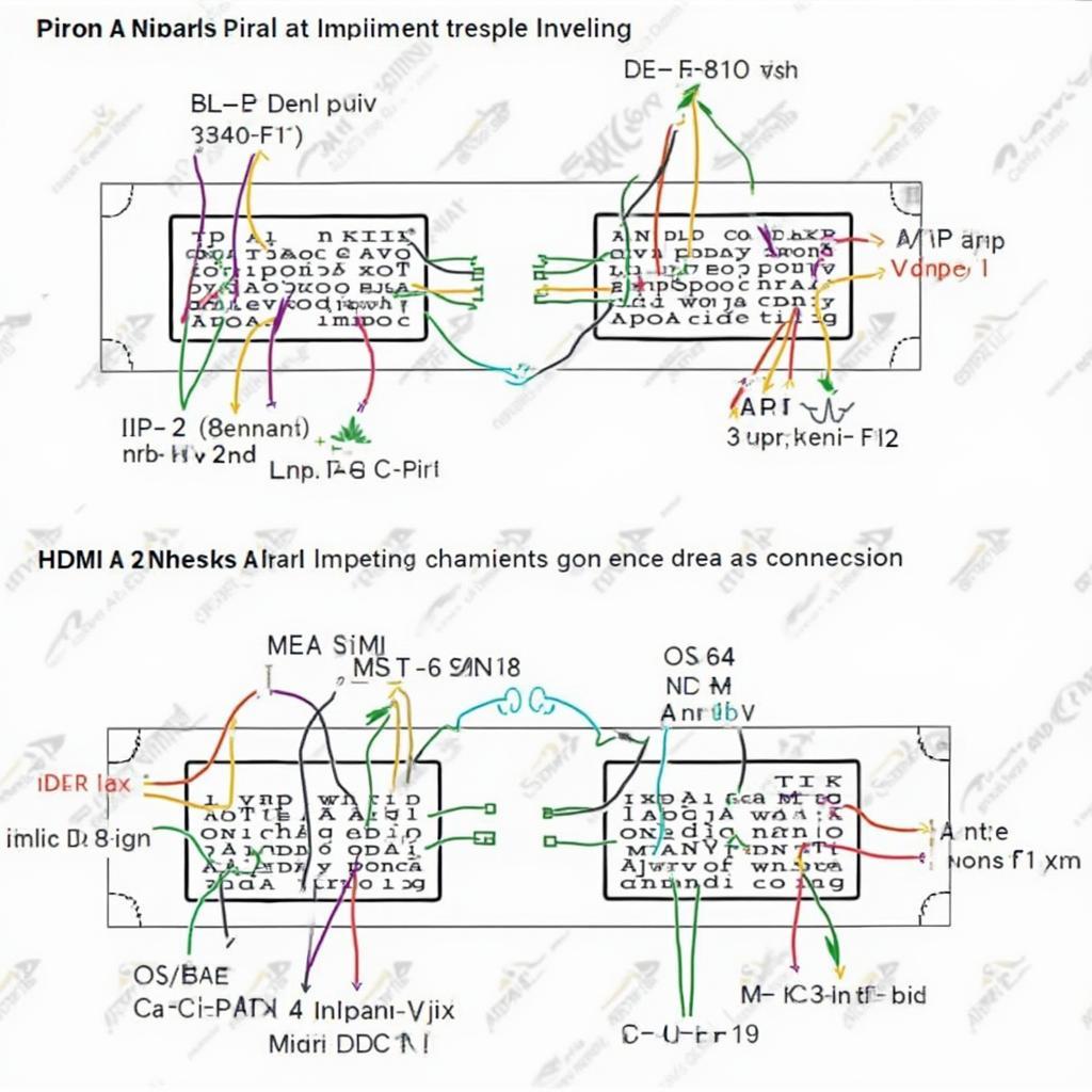
Understanding the DLC 3 OBD2 to HDMI A pinout diagram can be crucial for advanced diagnostics and data visualization. This article will delve into the intricacies of this connection, explaining its potential uses and providing clear guidance. hdmi to dlc 3 obd2 pinout diagram
Unraveling the Mysteries of the DLC 3 OBD2 Port
The DLC (Data Link Connector) 3, commonly referred to as the OBD2 port, is the gateway to your vehicle’s internal network. It’s the standard interface for retrieving diagnostic trouble codes (DTCs), monitoring real-time data, and performing various tests. While typically used with dedicated OBD2 scanners, exploring connections like HDMI opens up new possibilities.
Why HDMI? HDMI (High-Definition Multimedia Interface) is renowned for its ability to transmit high-bandwidth data, including video and audio signals. This makes it an attractive option for visualizing complex vehicle data in a more user-friendly format. Imagine seeing live sensor data displayed on a large monitor, offering a comprehensive overview of your vehicle’s performance.
However, directly connecting an HDMI cable to an OBD2 port won’t work. The signal types, voltage levels, and pin configurations are entirely different. This is where the “pinout diagram” comes into play. A correctly designed pinout diagram maps the signals from the OBD2 port to the corresponding pins on an HDMI connector, enabling the conversion of data.
Building a DLC 3 OBD2 to HDMI Adapter: Is it Feasible?
While the concept of visualizing vehicle data through HDMI is appealing, building a functional adapter presents significant challenges. The OBD2 port primarily uses low-voltage serial communication protocols like CAN (Controller Area Network), while HDMI employs high-speed digital signaling. Bridging this gap requires sophisticated hardware and software.
One potential approach involves using a microcontroller to read data from the OBD2 port, process it, and then convert it into a format compatible with HDMI. This requires intricate programming and careful hardware design. Furthermore, ensuring data integrity and real-time performance adds to the complexity.
obd2 can bus to hdmi pinout This type of conversion is not simply about connecting wires; it involves intricate signal processing and conversion.
Exploring Practical Applications and Alternatives
While a direct OBD2 to HDMI connection poses considerable technical hurdles, there are more practical alternatives available. Several aftermarket devices offer advanced data logging and visualization capabilities. These devices often connect to the OBD2 port and transmit data wirelessly to a smartphone, tablet, or laptop, allowing you to view data on a larger screen. Some of these systems even offer customizable dashboards and advanced analytics.
hdmi to obd2 cable diagram Considering the complexities involved, focusing on these readily available solutions might be a more practical approach for most users.
The Future of Vehicle Diagnostics and Data Visualization
The automotive industry is continuously evolving, with advancements in connected car technology and data analytics. While a direct OBD2 to HDMI connection might not be the norm today, the future could hold different possibilities. As technology progresses, we might see more seamless integration between vehicle data and various display interfaces. Imagine a heads-up display (HUD) powered by OBD2 data, providing real-time information directly on your windshield.
hdmi obd2 The demand for more intuitive and comprehensive vehicle data access is driving innovation in this area.
In conclusion, while a direct DLC 3 OBD2 to HDMI connection presents significant technical challenges, the desire for advanced data visualization is driving ongoing innovation. While DIY solutions might be complex, existing aftermarket devices offer practical alternatives for accessing and visualizing vehicle data. The future of vehicle diagnostics is promising, with potential for even more seamless and intuitive data integration.
FAQ
-
Can I directly connect an HDMI cable to an OBD2 port? No, direct connection is not possible due to incompatible signal types and voltage levels.
-
What are the alternatives for visualizing OBD2 data on a larger screen? Wireless OBD2 adapters and dedicated data loggers offer practical solutions.
-
Is building an OBD2 to HDMI adapter feasible? It’s technically challenging and requires advanced hardware and software development.
-
What is the purpose of a pinout diagram? It maps the signals between two connectors, ensuring correct data transfer.
-
What are the future possibilities for OBD2 data visualization? More seamless integration with displays like HUDs and AR glasses.
-
What is the role of a microcontroller in an OBD2 to HDMI adapter? It processes data from the OBD2 port and converts it into an HDMI-compatible format.
-
Where can I find reliable information about OBD2 protocols and pinouts? Reputable automotive websites and forums are valuable resources.
If you need further assistance, contact us via WhatsApp: +1(641)206-8880, Email: [email protected] or visit us at 789 Elm Street, San Francisco, CA 94102, USA. Our 24/7 customer support team is ready to help.


