The FlashScan OBD2 cable is an essential tool for vehicle diagnostics, allowing you to communicate with your car’s computer and access a wealth of information. At the heart of this communication lies the cable’s pinout – the specific arrangement of wires within the connector that determines how data is transmitted. Understanding the FlashScan OBD2 cable pinout is crucial for ensuring proper connections and maximizing the effectiveness of your diagnostic sessions.
Demystifying the OBD2 Standard
Before delving into the specifics of the FlashScan cable, let’s briefly review the OBD2 standard. OBD2, short for On-Board Diagnostics, second generation, is a standardized system for monitoring and diagnosing engine and emissions-related components in vehicles. Since 1996, most vehicles sold in the United States have been equipped with an OBD2 port, typically located under the dashboard on the driver’s side.
The OBD2 standard dictates a 16-pin connector, with each pin assigned a specific function. While some pins are standardized across all vehicles, others can vary depending on the manufacturer and communication protocols used.
Unraveling the FlashScan OBD2 Cable Pinout
The FlashScan OBD2 cable connects your diagnostic tool, typically a laptop or dedicated scanner, to your vehicle’s OBD2 port. This cable acts as a bridge, enabling seamless data transfer between the two systems.
The pinout of a FlashScan cable aligns with the standard OBD2 pinout, but it’s essential to use a cable specifically designed for FlashScan devices to ensure compatibility.
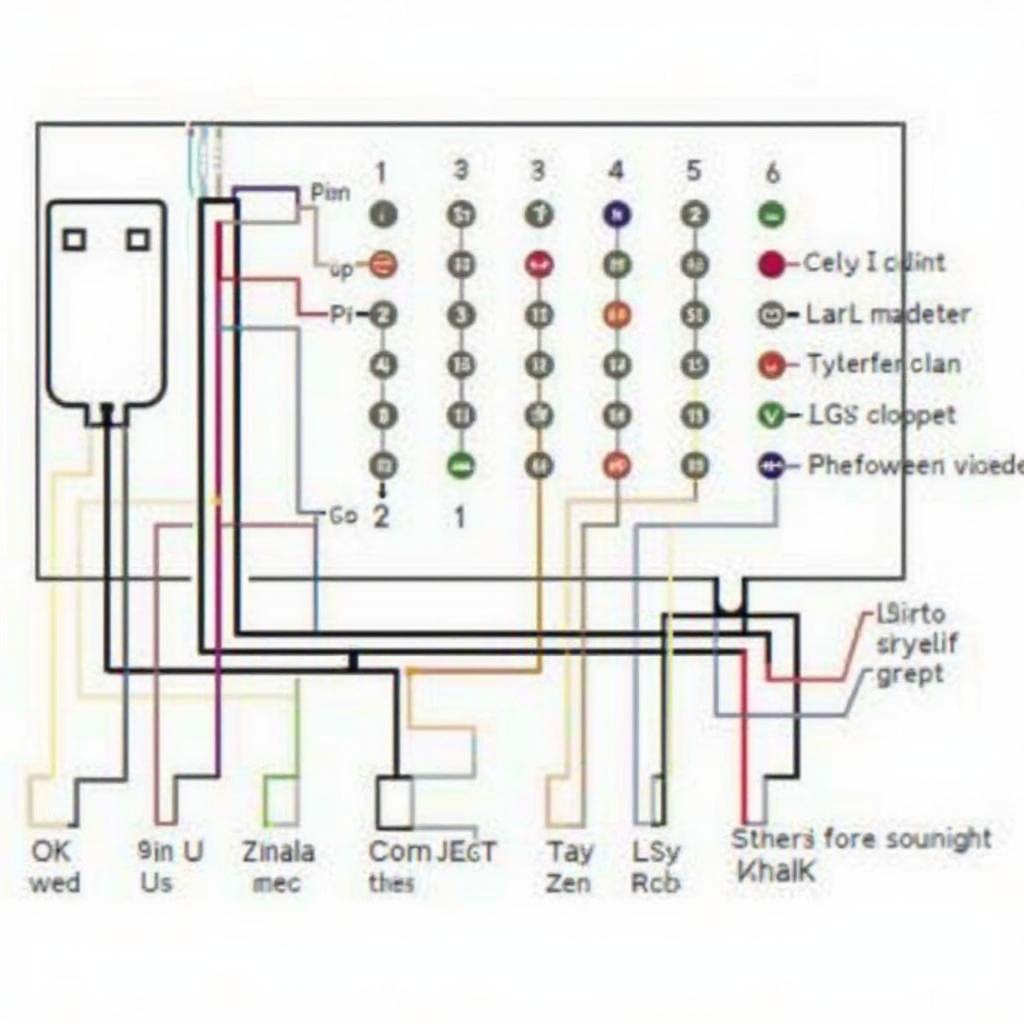
While the specific wire colors may differ slightly between cable manufacturers, the pin functions remain consistent. Here’s a breakdown of the FlashScan OBD2 cable pinout and the role of each pin:
- Pin 1: Manufacturer Discretionary – This pin’s function is determined by the vehicle manufacturer.
- Pin 2: J1850 Bus+ – Used for communication on the J1850 Bus, primarily found in Ford vehicles.
- Pin 3: Manufacturer Discretionary – This pin’s function is determined by the vehicle manufacturer.
- Pin 4: Chassis Ground – Provides a ground connection for the chassis.
- Pin 5: Signal Ground – Provides a ground connection for the signal circuits.
- Pin 6: CAN High (CAN H) – Used for communication on the Controller Area Network (CAN) bus, a high-speed communication protocol.
- Pin 7: ISO 9141-2 K-Line – Used for communication using the ISO 9141-2 protocol, often found in European and Asian vehicles.
- Pin 8: CAN Low (CAN L) – Complements CAN High for communication on the CAN bus.
- Pin 9: Manufacturer Discretionary – This pin’s function is determined by the vehicle manufacturer.
- Pin 10: J1850 Bus- – Complements J1850 Bus+ for communication on the J1850 Bus.
- Pin 11: Manufacturer Discretionary – This pin’s function is determined by the vehicle manufacturer.
- Pin 12: Manufacturer Discretionary – This pin’s function is determined by the vehicle manufacturer.
- Pin 13: Manufacturer Discretionary – This pin’s function is determined by the vehicle manufacturer.
- Pin 14: CAN High (CAN H) – A secondary CAN High pin for additional modules or communication lines.
- Pin 15: ISO 9141-2 L-Line – Complements ISO 9141-2 K-Line for communication using the ISO 9141-2 protocol.
- Pin 16: Battery Voltage – Provides a direct connection to the vehicle’s battery voltage.
Common FlashScan OBD2 Cable Pinout Questions Answered
What is the purpose of the CAN High and CAN Low pins?
The CAN High and CAN Low pins work together to transmit data on the Controller Area Network (CAN) bus. This high-speed communication protocol allows various modules within the vehicle to exchange information efficiently.
Why are some pins labeled “Manufacturer Discretionary”?
Vehicle manufacturers have the flexibility to use certain pins for specific functions tailored to their vehicles. These functions might include communication with proprietary modules, accessing unique diagnostic data, or even controlling certain vehicle features.
Can I use any OBD2 cable with my FlashScan device?
While all OBD2 cables might look similar, it’s crucial to use a cable specifically designed and tested for compatibility with FlashScan devices. Using an incompatible cable could lead to communication errors, inaccurate data readings, or even potential damage to your diagnostic tool or vehicle.
“Using the right cable is paramount,” says automotive electronics expert Michael Carter. “It’s not just about making a connection; it’s about ensuring reliable and accurate data transmission, which is fundamental for effective vehicle diagnostics.”
Conclusion
Understanding the FlashScan OBD2 cable pinout empowers you to delve deeper into vehicle diagnostics. With this knowledge, you can confidently connect your FlashScan device, interpret communication protocols, and unlock a wealth of information about your vehicle’s health and performance. Remember, using a compatible and reliable cable is essential for accurate diagnostics and optimal results. If you have any doubts or require assistance, don’t hesitate to contact our expert team through WhatsApp: +1(641)206-8880 or Email: [email protected]. We are available 24/7 to assist you.


