Understanding the HDMI to DLC 3 OBD2 pinout diagram is crucial for anyone working with vehicle diagnostics. This guide provides a deep dive into the intricacies of this connection, offering valuable insights for both professionals and car enthusiasts alike.
Decoding the HDMI to DLC 3 OBD2 Connection
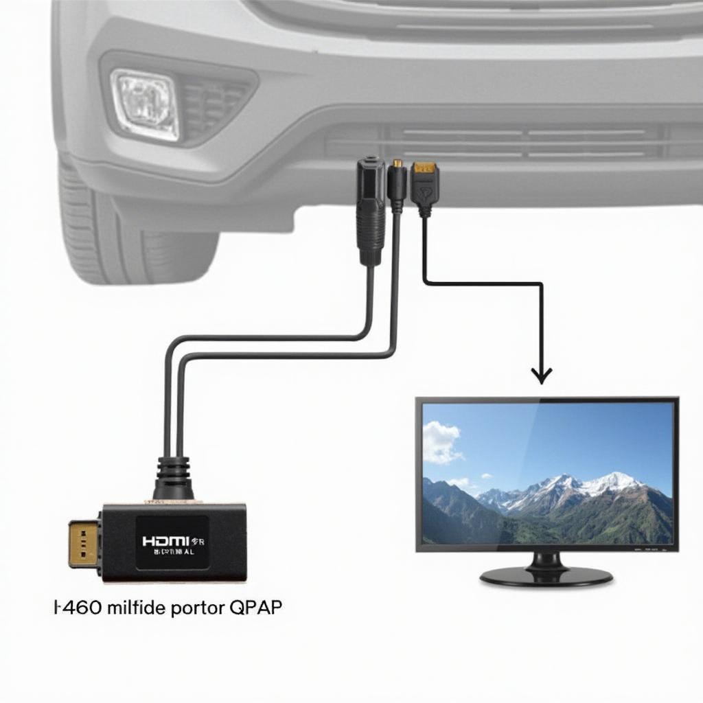
While the phrase “HDMI to DLC 3 OBD2” might seem confusing at first, it points to a specific need: displaying OBD2 data on a screen with an HDMI input. A direct HDMI connection to the OBD2 port isn’t standard. The OBD2 port uses a 16-pin DLC (Data Link Connector) and transmits data using specific protocols, not HDMI signals. Therefore, an interface device is required to convert the OBD2 data into an HDMI-compatible format. This device acts as a bridge, allowing you to view diagnostic information on a monitor or other HDMI display.
Why Use an HDMI to OBD2 Interface?
Using an HDMI interface with your OBD2 scanner offers several advantages. Larger displays provide a clearer view of data, making it easier to analyze complex information. This is especially beneficial for professional mechanics. Moreover, HDMI interfaces often offer features like data logging and playback, enabling in-depth analysis and troubleshooting.
Understanding the OBD2 Pinout Diagram
The OBD2 port’s 16 pins each have a specific function. Knowing the pinout diagram is essential for understanding how data is transmitted and received. While not directly related to the HDMI output, it’s fundamental to the entire process.
Key OBD2 Pins and Their Functions
Some key pins include:
- Pin 2 (J1850+ Bus Positive): Used for communication on certain vehicle makes.
- Pin 4 (Chassis Ground): Provides a ground connection for the system.
- Pin 5 (Signal Ground): A separate ground for signal circuits.
- Pin 6 (CAN High): Used for Controller Area Network (CAN) communication.
- Pin 7 (ISO 9141-2 K-Line): Another communication protocol line.
- Pin 14 (CAN Low): Completes the CAN communication circuit.
- Pin 16 (Battery Power): Supplies power to the OBD2 device.
Choosing the Right HDMI to OBD2 Interface
Selecting the right interface depends on your specific needs. Consider factors like compatibility with your vehicle’s make and model, supported OBD2 protocols, and additional features like data logging and real-time display capabilities.
Compatibility and Functionality
Ensure the interface supports the protocols used by your vehicle. Also, consider the resolution and refresh rate of the HDMI output for optimal viewing on your display.
Troubleshooting Common HDMI to OBD2 Issues
Occasionally, you may encounter problems like no display or data errors. Checking the connections, ensuring proper power supply, and verifying compatibility are crucial troubleshooting steps.
No Display on the Monitor
If you encounter a blank screen, check the HDMI cable connection and ensure the interface device is powered on. Try a different HDMI cable and monitor to isolate the issue.
Conclusion
Utilizing an HDMI to DLC 3 OBD2 interface enhances your diagnostic capabilities by providing a larger, clearer display of critical vehicle data. Understanding the OBD2 pinout diagram and choosing the right interface are crucial steps for successful implementation. This allows for more effective diagnostics and a better understanding of your vehicle’s performance.
FAQ
- What is the purpose of an HDMI to OBD2 interface? It converts OBD2 data into an HDMI-compatible format for display on a monitor.
- Do all vehicles use the same OBD2 protocols? No, different makes and models may use different protocols.
- Is a direct HDMI connection to the OBD2 port possible? No, an interface device is necessary.
- What should I do if there is no display on my monitor? Check connections, power supply, and try a different cable and monitor.
- Where can I find a reliable HDMI to OBD2 interface? Check reputable online retailers and automotive parts suppliers.
- What are the benefits of using a larger display for OBD2 data? Improved visibility and easier analysis of complex information.
- Is knowing the OBD2 pinout diagram important when using an HDMI interface? While not directly related to HDMI, understanding the OBD2 port is fundamental to the diagnostic process.
You can also explore other related articles on our website for more information on OBD2 scanners, diagnostic tools, and vehicle maintenance.
Need further assistance? Contact us via WhatsApp: +1(641)206-8880 or Email: [email protected]. Our customer support team is available 24/7.


