Locating and understanding your Honda’s OBD2 data link connector (DLC) is essential for diagnosing and troubleshooting car problems. This connector provides a wealth of information about your vehicle’s engine, transmission, emissions, and other crucial systems. This comprehensive guide will walk you through everything you need to know about the Honda OBD2 data link connector pinout, its location, and how to use it effectively.
Understanding the OBD2 Data Link Connector
The OBD2 DLC, often referred to as the OBD2 port, is a standardized 16-pin connector found in most vehicles manufactured after 1996. This port serves as the communication gateway between your Honda’s onboard computer and external diagnostic tools, such as OBD2 scanners.
Locating the Honda OBD2 Connector
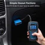
In most Honda models, the OBD2 connector is located under the driver’s side dashboard, typically within reach of the steering wheel. It’s usually a black or gray rectangular connector with a 16-pin configuration. However, the exact location might vary slightly depending on the model year and region.
Here’s a general guideline for finding the OBD2 connector in your Honda:
- Start by looking under the driver’s side dashboard. This is the most common location for the connector.
- Check the area around the steering column, fuse box, and ashtray. The connector might be tucked away in these areas.
- Look for a trapezoidal-shaped connector with 16 pins. The connector is usually black or gray and might have a cover labeled “Diagnostic” or “OBD2.”
If you’re still having trouble finding the connector, consult your owner’s manual or perform a quick online search for your specific Honda model.
Honda OBD2 Pinout Diagram Explained
Each pin in the OBD2 connector has a specific function, allowing communication between your Honda’s various systems and the diagnostic tool. While most pins are standardized across vehicle manufacturers, some pins are manufacturer-specific and used for communication protocols unique to Honda.
Here’s a breakdown of the Honda OBD2 pinout diagram:
- Pin 1: Used for manufacturer-specific protocols and communication.
- Pin 2: J1850 Bus+ (for vehicles using the J1850 PWM protocol).
- Pin 3: Not used in Honda vehicles.
- Pin 4: Chassis Ground.
- Pin 5: Signal Ground.
- Pin 6: CAN High (J-2284).
- Pin 7: ISO 9141-2 K-Line (for vehicles using the ISO 9141-2 protocol).
- Pin 8: Not used in Honda vehicles.
- Pin 9: Not used in Honda vehicles.
- Pin 10: J1850 Bus- (for vehicles using the J1850 PWM protocol).
- Pin 11: Not used in Honda vehicles.
- Pin 12: Not used in Honda vehicles.
- Pin 13: Not used in Honda vehicles.
- Pin 14: CAN Low (J-2284).
- Pin 15: ISO 9141-2 L-Line (for vehicles using the ISO 9141-2 protocol).
- Pin 16: Battery Voltage.
Using the Honda OBD2 Connector for Diagnostics
The Honda OBD2 connector provides a gateway to access valuable information about your vehicle’s health and performance. By connecting an OBD2 scanner, you can:
- Read and clear diagnostic trouble codes (DTCs): DTCs are stored in your Honda’s onboard computer when a problem is detected, and understanding these codes can pinpoint the root cause of an issue.
- View live data streams: Monitor real-time sensor readings, such as engine RPM, coolant temperature, oxygen sensor voltage, and more, providing insights into your vehicle’s performance.
- Perform advanced diagnostics: Certain scanners offer advanced features like bi-directional control, allowing you to activate components like actuators and solenoids for more in-depth troubleshooting.
Conclusion
Understanding your Honda’s OBD2 data link connector pinout is crucial for effective vehicle diagnostics and maintenance. By knowing its location, pin functions, and how to use it with an OBD2 scanner, you can gain valuable insights into your car’s health, troubleshoot problems, and ensure optimal performance.

