Understanding how to wire an OBD2 connector is crucial for any car enthusiast or professional mechanic. Whether you’re troubleshooting a check engine light, installing a new car accessory, or building a custom diagnostics tool, knowing the OBD2 connector pinout is essential. This article will provide a comprehensive guide on how to wire an OBD2 connector, covering everything from basic pin identification to advanced wiring techniques.
Connecting an OBD2 scanner can seem daunting, but with a little knowledge, it’s a manageable task. We’ll explore the function of each pin, common wiring issues, and best practices for a safe and successful connection. This guide will empower you to confidently tackle OBD2 wiring projects and unlock the full potential of your vehicle’s diagnostic system. Let’s dive in! For more information on connecting specific devices, you might find our article on the obd2 wireless connector helpful.
Understanding the OBD2 Connector Pinout
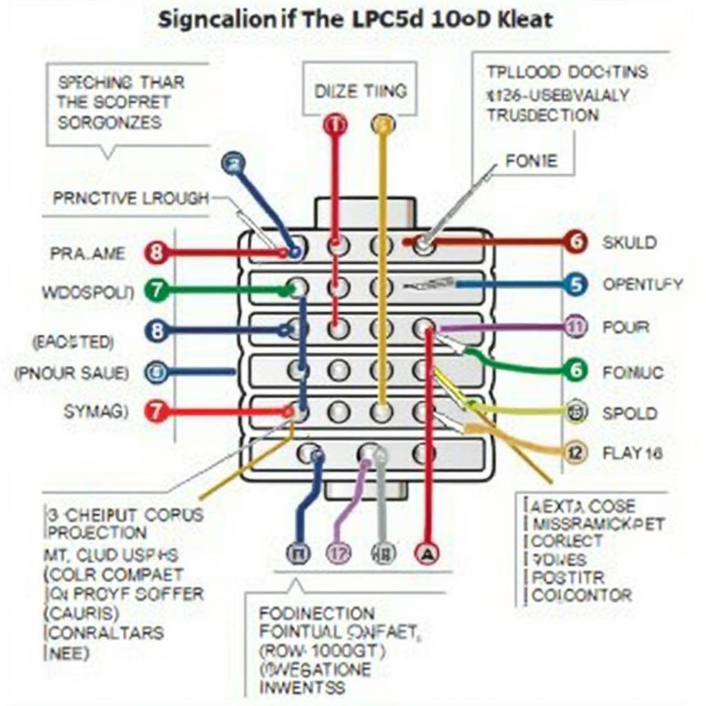
The OBD2 connector, a standardized 16-pin port, is the gateway to your vehicle’s diagnostic system. Each pin has a specific function, and understanding these functions is the first step in wiring the connector correctly.
Pin Functions and Identification
The 16 pins are arranged in two rows of eight and are numbered from 1 to 16, starting from the top left corner. While not all pins are used in every vehicle, some are crucial for basic communication and power supply. Here’s a breakdown of the standard OBD2 pinout:
- Pin 1: Used for manufacturer-specific protocols.
- Pin 2: J1850 Bus+ (used by some Ford vehicles).
- Pin 3: Not used.
- Pin 4: Chassis Ground.
- Pin 5: Signal Ground.
- Pin 6: CAN High (Controller Area Network).
- Pin 7: ISO 9141-2 K-Line.
- Pin 8: Not used.
- Pin 9: Not used.
- Pin 10: J1850 Bus- (used by some GM vehicles).
- Pin 11: Not used.
- Pin 12: Not used.
- Pin 13: Not used.
- Pin 14: CAN Low (Controller Area Network).
- Pin 15: ISO 9141-2 L-Line.
- Pin 16: Battery Power (12V).
Wiring the OBD2 Connector
Now that you understand the pinout, let’s discuss how to wire the OBD2 connector for different applications.
Wiring for Basic Diagnostics
For basic diagnostics using a standard OBD2 scanner, you’ll primarily need to connect the power, ground, and communication lines. This usually involves pins 4 (Chassis Ground), 5 (Signal Ground), 16 (Battery Power), and one or two communication pins depending on the vehicle’s protocol (e.g., pins 6 and 14 for CAN, pin 7 for ISO 9141-2). If you’re working with a specific vehicle and encounter limited wiring, you can find more information on situations like an only 4 wires in obd2 connector of 04 yukon.
Wiring for Custom Applications
Wiring for custom applications, such as building your own diagnostic tool, requires a more in-depth understanding of the vehicle’s communication protocols. Ensure you have a detailed wiring diagram specific to your project and vehicle. Using jumper wire male to male obd2 connector pinout can be extremely helpful for these types of projects.
Best Practices for OBD2 Wiring
- Use the Correct Gauge Wire: Use the appropriate wire gauge for the current draw of your application. Using undersized wire can lead to overheating and potential fire hazards.
- Properly Crimp and Solder Connections: Ensure all connections are securely crimped or soldered to prevent intermittent connections.
- Use Heat Shrink Tubing: Protect your connections with heat shrink tubing to prevent short circuits and corrosion.
- Consult Vehicle-Specific Wiring Diagrams: Always refer to your vehicle’s wiring diagram for accurate pin assignments and to avoid damaging the vehicle’s electrical system.
“Always double-check your wiring before applying power. A simple mistake can damage sensitive electronic components,” advises John Smith, Senior Automotive Electrical Engineer at Acme Automotive Solutions.
Troubleshooting Common OBD2 Wiring Issues
Sometimes, even with careful planning, you may encounter wiring issues. Here are some common problems and solutions:
- No Power to the OBD2 Connector: Check the fuse for the OBD2 port.
- Intermittent Connection: Check for loose or corroded connections.
- Incorrect Communication: Verify the correct communication protocol for your vehicle and ensure the correct pins are connected.
“Regularly inspecting and cleaning your OBD2 connector can prevent many common wiring problems,” adds Jane Doe, Certified Automotive Technician at Speedy Auto Repairs.
Conclusion
Wiring an OBD2 connector can be straightforward with the right knowledge and tools. Understanding the pinout, adhering to best practices, and being prepared to troubleshoot will help you successfully connect your diagnostic tools or custom applications. Mastering how to wire an OBD2 connector empowers you to take control of your vehicle’s diagnostics and unlock valuable insights into its performance. For more specific OBD2 code information, check out our resources on codes like obd2 p1674 and p0030 obd2 code.
FAQ
- What is the purpose of the OBD2 connector? The OBD2 connector provides access to your vehicle’s diagnostic system, allowing you to read and clear trouble codes, monitor sensor data, and perform other diagnostic functions.
- How many pins are in an OBD2 connector? An OBD2 connector has 16 pins.
- Are all OBD2 pins used in every vehicle? No, not all pins are used in every vehicle. Some pins are reserved for manufacturer-specific protocols.
- What is the voltage of the OBD2 power pin? The OBD2 power pin (pin 16) provides 12V battery power.
- Where can I find the OBD2 connector in my vehicle? The OBD2 connector is typically located under the dashboard, near the steering column.
- What is CAN communication? CAN (Controller Area Network) is a high-speed communication protocol used by many modern vehicles.
- Do I need special tools to wire an OBD2 connector? Basic wiring tools like wire strippers, crimpers, and a multimeter are recommended.
Need help with your OBD2 connector wiring or have further questions? Contact us via WhatsApp: +1(641)206-8880, Email: cardiagtechworkshop@gmail.com or visit our office at 789 Elm Street, San Francisco, CA 94102, USA. Our 24/7 customer support team is ready to assist you.


