OBD2 connector adapter schematics are essential for anyone working with vehicle diagnostics. Understanding these schematics allows you to troubleshoot connection issues, create custom adapters, and gain a deeper understanding of how your OBD2 scanner communicates with your vehicle. This article will delve into the intricacies of OBD2 connector pinouts, common adapter types, and practical applications of these schematics.
Decoding the OBD2 Connector Pinout: Your Gateway to Vehicle Data
The standardized OBD2 connector, officially known as SAE J1962, features a 16-pin trapezoidal design. Each pin has a specific function, ranging from power supply to communication lines. Understanding this pinout is crucial for interpreting obd2 connector adapter schematics.
- Pin 1: Not used in most vehicles.
- Pin 2: J1850 Bus+ (used by some Ford vehicles).
- Pin 3: Not used in most vehicles.
- Pin 4: Chassis Ground.
- Pin 5: Signal Ground.
- Pin 6: CAN High (J-2284).
- Pin 7: ISO 9141-2 K-Line (used by some Chrysler, European, and Asian vehicles).
- Pin 8: Not used in most vehicles.
- Pin 9: Not used in most vehicles.
- Pin 10: J1850 Bus- (used by some Ford vehicles).
- Pin 11: Not used in most vehicles.
- Pin 12: Not used in most vehicles.
- Pin 13: Not used in most vehicles.
- Pin 14: CAN Low (J-2284).
- Pin 15: ISO 9141-2 L-Line (used by some Chrysler, European, and Asian vehicles).
- Pin 16: Battery Power (12V).
Common OBD2 Connector Adapter Types and Their Schematics
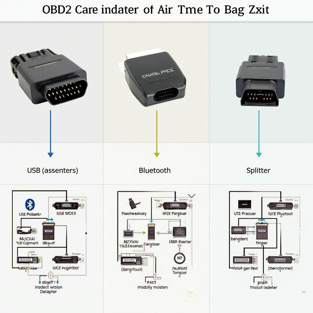
Various OBD2 adapters exist to cater to different diagnostic needs. Understanding their schematics helps choose the right adapter for your specific application.
OBD2 to USB Adapter
These adapters are widely used for connecting OBD2 scanners to laptops and PCs. Their schematics typically involve converting the OBD2 signals to USB format.
OBD2 to Bluetooth Adapter
Bluetooth adapters enable wireless communication between your vehicle and diagnostic tools like smartphones and tablets. The schematic highlights the Bluetooth module’s integration with the OBD2 interface.
OBD2 Splitter/Extension Cable
These adapters allow connecting multiple devices to the OBD2 port simultaneously or extending the reach of the OBD2 connector. The schematic is straightforward, showing a direct connection between pins.
Practical Applications of OBD2 Connector Adapter Schematics: Troubleshooting and Customization
Knowing how to read obd2 connector adapter schematics empowers you to:
- Troubleshoot Connection Issues: If your scanner isn’t communicating with your vehicle, a schematic can help identify potential wiring problems or pin mismatches.
- Build Custom Adapters: You can create specialized adapters for unique diagnostic tasks by understanding the pinout and signal requirements.
- Integrate with Other Systems: Schematics are crucial for integrating OBD2 data with other vehicle systems or data logging devices.
“Understanding OBD2 schematics is like having a roadmap to your vehicle’s data,” says Alex Thompson, Senior Automotive Diagnostic Technician at AutoTech Solutions. “It opens up a world of possibilities for troubleshooting and customization.”
Why are OBD2 Adapter Schematics Important?
OBD2 adapter schematics are important because they provide a visual representation of the electrical connections between the OBD2 port and the adapter. This information is essential for understanding how the adapter works and for troubleshooting any problems that may arise.
“Having a readily available schematic can save valuable time when diagnosing a faulty connection,” adds Maria Sanchez, Lead Electrical Engineer at Car Diagnostics Inc. “It’s a crucial tool for any serious automotive professional.”
Conclusion
OBD2 connector adapter schematics are indispensable for anyone working with vehicle diagnostics. They offer a deep understanding of the communication between your scanner and vehicle, allowing for effective troubleshooting, custom adapter creation, and system integration. Mastering these schematics is a key step towards becoming proficient in vehicle diagnostics and unlocking the full potential of your OBD2 scanner.
FAQ
-
What is the purpose of the OBD2 connector? The OBD2 connector provides a standardized interface for accessing vehicle diagnostic information.
-
Are all OBD2 connectors the same? Yes, the physical connector is standardized, but the communication protocols used can vary depending on the vehicle’s make and model.
-
Where can I find OBD2 connector adapter schematics? You can find schematics online, in vehicle repair manuals, and from adapter manufacturers.
-
Can I damage my vehicle by using the wrong OBD2 adapter? It’s unlikely to damage your vehicle with an incorrect adapter, but it might not function correctly or provide accurate data.
-
What is CAN bus in OBD2? CAN bus is a communication protocol used in many modern vehicles for transmitting data between various electronic control units (ECUs).
-
What are the different OBD2 protocols? Several OBD2 protocols exist, including SAE J1850 PWM, SAE J1850 VPW, ISO 9141-2, ISO 14230-4 KWP2000, and CAN bus.
-
What is the difference between Pin 4 and Pin 5 on the OBD2 connector? Pin 4 is the chassis ground, while Pin 5 is the signal ground. Both are essential for proper circuit operation.
Need help with your OBD2 Scanner? Contact us via WhatsApp: +1(641)206-8880, Email: [email protected] or visit our office at 789 Elm Street, San Francisco, CA 94102, USA. Our 24/7 customer support team is ready to assist you.


