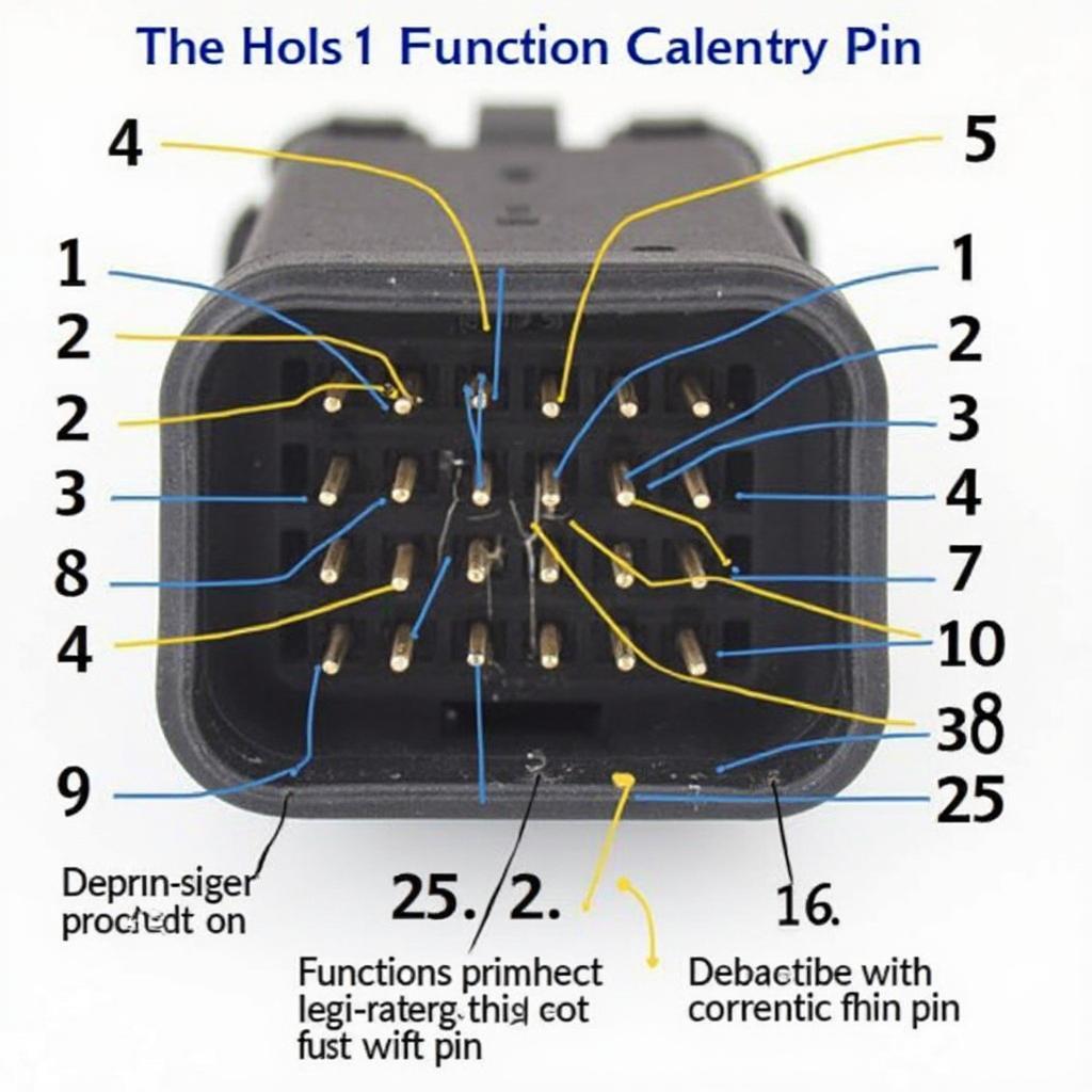
The OBD2 connector, a 16-pin trapezoidal port, serves as the gateway to your car’s onboard diagnostics system. Understanding the OBD2 connector pin layout is crucial for anyone who wants to delve into the world of vehicle diagnostics, whether you’re a seasoned mechanic or a curious car owner. This article will provide a comprehensive guide to the OBD2 pinout, explaining the function of each pin and its significance in retrieving valuable diagnostic information.
Decoding the OBD2 Pinout
Each of the 16 pins in the OBD2 connector has a specific function, facilitating communication between the vehicle’s electronic control units (ECUs) and diagnostic tools.
Pin 1: Manufacturer Discretionary Use
This pin allows manufacturers to incorporate specific diagnostic functions unique to their vehicles. While not standardized across all makes and models, it often relates to the vehicle’s network communication.
Pin 2: J1850 Bus+ (SAE J1850 PWM and VPW)
Primarily used by Ford and some Chrysler models, this pin carries the positive signal for the J1850 communication protocol.
Pin 3: Manufacturer Discretionary Use
Similar to pin 1, this pin is reserved for manufacturer-specific functionalities.
Pin 4: Chassis Ground
As the name suggests, this pin provides a ground connection for the vehicle’s chassis, ensuring proper voltage levels for communication.
Pin 5: Signal Ground
This pin serves as the ground reference for the various signals transmitted through the OBD2 connector.
Pin 6: CAN High (CAN C)
Part of the Controller Area Network (CAN) bus system, this pin carries the high-speed data signal for communication between ECUs.
Pin 7: ISO 9141-2 K-Line
Used in older vehicles, particularly those from European manufacturers, this pin facilitates communication using the ISO 9141-2 protocol.
Pin 8: Battery Power
This pin provides a direct connection to the vehicle’s battery, supplying power to the connected diagnostic tool.
 OBD2 Connector Pin Layout
Pin 9: Manufacturer Discretionary Use
Another manufacturer-specific pin, often used for communication protocols unique to certain vehicle makes.
Pin 10: SAE J1850 Bus- (SAE J1850 PWM and VPW)
Complementary to pin 2, this pin carries the negative signal for the J1850 communication protocol used in Ford and some Chrysler vehicles.
Pin 11: Manufacturer Discretionary Use
Similar to pins 1, 3, and 9, this pin allows for manufacturer-specific functionalities.
Pin 12: Manufacturer Discretionary Use
This pin, like the other manufacturer-specific pins, can be utilized for various purposes depending on the vehicle make and model.
Pin 13: Manufacturer Discretionary Use
Manufacturers have the flexibility to assign specific functions to this pin based on their vehicle’s diagnostic requirements.
Pin 14: CAN Low (CAN L)
Completing the CAN bus system, this pin carries the low-speed data signal for communication between the vehicle’s ECUs.
Pin 15: ISO 9141-2 L-Line
Working in conjunction with pin 7, this pin serves as the data line for the ISO 9141-2 communication protocol.
Pin 16: Battery Positive
Providing a redundant power source, this pin, along with pin 8, ensures the connected diagnostic tool has sufficient power for operation.
Significance of the OBD2 Connector Pin Layout
Understanding the OBD2 connector pin layout is essential for:
- Accurate Diagnostics: Identifying the correct pins for communication ensures accurate retrieval of diagnostic trouble codes (DTCs) and live data from the vehicle’s ECUs.
- Protocol Compatibility: Different vehicle manufacturers use various communication protocols. Knowing the pin layout helps determine the appropriate protocol for your vehicle and select compatible diagnostic tools.
- Advanced Troubleshooting: Familiarity with the pinout allows for more advanced troubleshooting by directly accessing specific ECUs and sensors through customized wiring harnesses.
“Understanding the OBD2 pin layout is like having a roadmap to your car’s brain,” says John Smith, a veteran automotive engineer. “It allows you to tap into the intricate network of sensors and ECUs, unlocking a wealth of information about your vehicle’s health and performance.”
FAQs about OBD2 Connector Pin Layout
Q: Can I damage my car by connecting to the wrong pins?
A: While unlikely, connecting to the wrong pins with improper voltage or signals could potentially damage your vehicle’s electronics. It’s crucial to use compatible diagnostic tools and avoid tampering with the connector’s wiring.
Q: Do all vehicles use the same communication protocol?
A: No, different manufacturers use various protocols like CAN, J1850, and ISO 9141-2. Knowing your vehicle’s specific protocol is essential for selecting compatible diagnostic equipment.
Q: Can I access manufacturer-specific functions through the OBD2 port?
A: While the standard OBD2 pin layout defines specific functions for most pins, manufacturers can assign unique functionalities to dedicated pins. Accessing these features often requires specialized software or diagnostic tools.
Conclusion
The OBD2 connector pin layout provides a standardized interface for accessing your vehicle’s diagnostic information. Understanding the function of each pin is crucial for accurate diagnostics, protocol compatibility, and advanced troubleshooting. By familiarizing yourself with the OBD2 pinout, you can confidently delve into the world of vehicle diagnostics, whether you’re a professional mechanic or a car enthusiast seeking to unravel the mysteries of your automobile.
If you want to learn more about OBD2 connectors, you can find additional information on OBD2 connector female, depin obd2 ecu connector and obd2 connector name. For troubleshooting specific vehicle issues, you might find resources like 2007 ford f150 obd2 fuse location utube helpful. And if you’re looking for information on OBD2 diagnostics displays, be sure to check out obd2 diagnostics display.

