The OBD2 connector wiring diagram is essential for anyone working with vehicle diagnostics. Whether you’re a professional mechanic or a DIY enthusiast, understanding this diagram allows you to effectively troubleshoot car problems, access valuable vehicle data, and utilize the full potential of your OBD2 scanner. This article will delve into the intricacies of the OBD2 connector, exploring its pinouts, protocols, and common applications.
Understanding the OBD2 connector wiring diagram is like having a roadmap to your car’s internal systems. Each pin on the connector corresponds to a specific function, allowing your OBD2 scanner to communicate with the various electronic control units (ECUs) within the vehicle. This communication enables the retrieval of diagnostic trouble codes (DTCs), real-time data monitoring, and even the ability to perform certain bi-directional controls. You can find useful resources on our site regarding specific OBD2 codes, such as can obd2 codes p0133.
Decoding the OBD2 Pinout
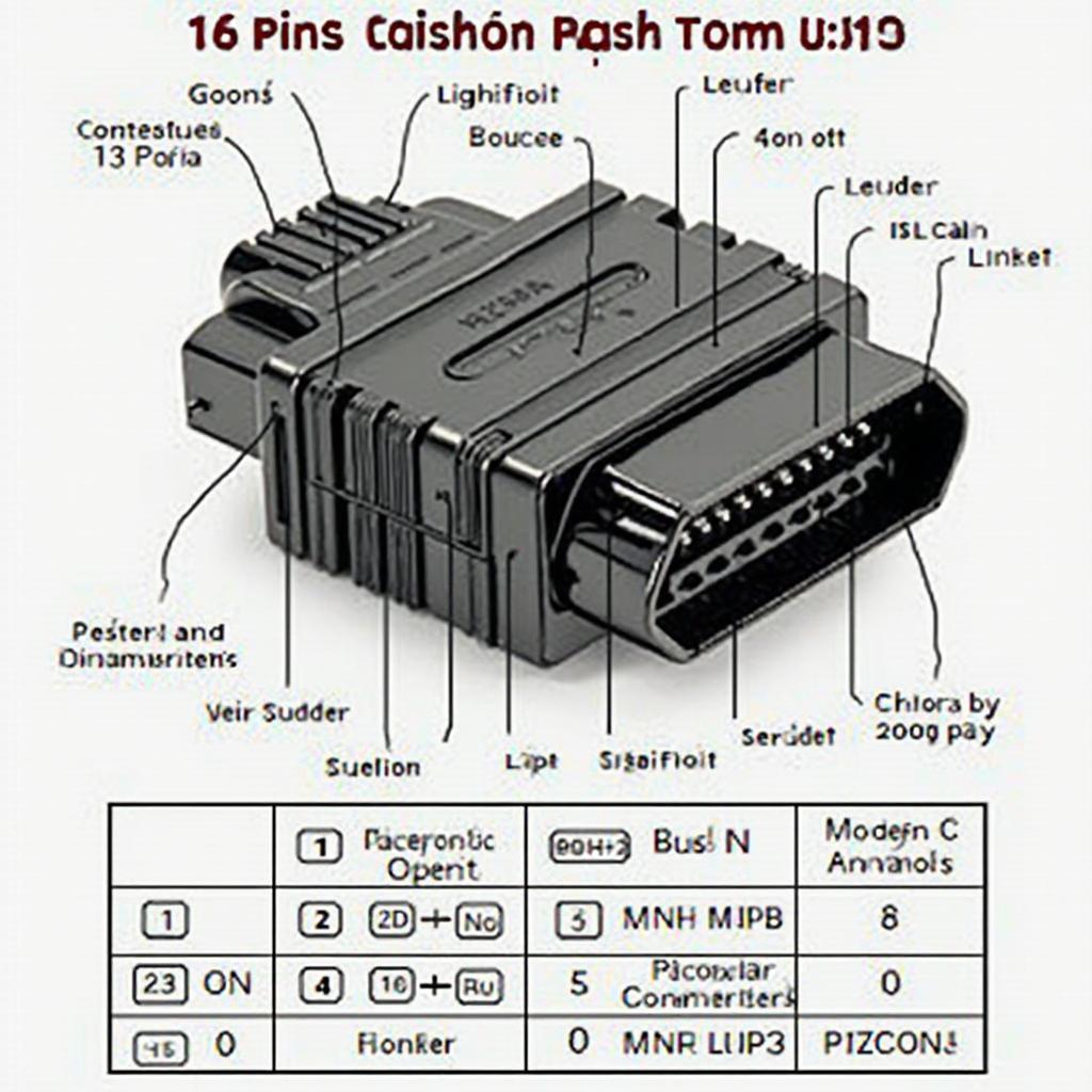
The OBD2 connector, a standardized 16-pin interface, is the gateway to your vehicle’s diagnostic system. Each pin has a designated purpose, and understanding these assignments is crucial. Here’s a breakdown of the standard OBD2 pinout:
- Pin 1: Manufacturer Discretionary
- Pin 2: J1850 Bus+ (Ford & GM)
- Pin 3: Manufacturer Discretionary
- Pin 4: Chassis Ground
- Pin 5: Signal Ground
- Pin 6: CAN High (J-2284)
- Pin 7: ISO 9141-2 K-Line
- Pin 8: Manufacturer Discretionary
- Pin 9: Manufacturer Discretionary
- Pin 10: J1850 Bus- (Ford & GM)
- Pin 11: Manufacturer Discretionary
- Pin 12: Manufacturer Discretionary
- Pin 13: Manufacturer Discretionary
- Pin 14: CAN Low (J-2284)
- Pin 15: ISO 9141-2 L-Line
- Pin 16: Battery Power (12V)
While this represents the standard configuration, some manufacturers may use discretionary pins for specific vehicle functionalities. Therefore, consulting your vehicle’s specific wiring diagram is always recommended.
Common OBD2 Communication Protocols
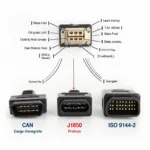
The OBD2 standard utilizes several communication protocols to transmit data between the scanner and the vehicle’s ECUs. Understanding these protocols helps you select the right scanner and interpret the data correctly. The most common protocols include:
- CAN (Controller Area Network): A high-speed, robust communication system used in most modern vehicles.
- J1850: Primarily used by Ford and GM vehicles.
- ISO 9141-2: Commonly found in older European and Asian vehicles.
Different vehicles may use different protocols, and some even employ multiple protocols simultaneously. If you’re experiencing issues with a specific PID, you can learn more on our website through articles like obd2 pid stopped working.
Why is the OBD2 Connector Wiring Diagram Important?
The OBD2 connector wiring diagram is essential for several reasons:
- Troubleshooting: Identifying the correct pins for power and communication lines is crucial for successful diagnostics.
- Advanced Diagnostics: Accessing specific data streams or controlling certain functions requires understanding the pin assignments.
- DIY Repairs: For those inclined towards DIY repairs, a solid understanding of the wiring diagram can be invaluable.
Using the OBD2 Wiring Diagram for Diagnostics
Knowing the obd2 connector wiring diagram is the first step. Let’s delve into how to actually use this knowledge for practical diagnostics:
- Locate the OBD2 port: Typically found under the dashboard on the driver’s side.
- Connect your OBD2 scanner: Ensure a secure connection.
- Turn the ignition on: Do not start the engine unless instructed by the scanner or diagnostic procedure.
- Access the desired data: Use your scanner to retrieve DTCs, view live data, or perform specific functions based on your understanding of the wiring diagram. For instance, checking the continuity of your OBD2 connection might be necessary. More information about this can be found on our page dedicated to obd2-code contituniy tester.
What if my OBD2 port isn’t working?
Sometimes, issues arise with the OBD2 port itself. Understanding the wiring diagram helps diagnose these problems. Check for damaged wires, blown fuses, or loose connections. A resource that may be helpful in such situations is our article on crx obd0 obd2 harness.
“Understanding the OBD2 wiring diagram is like learning a new language,” says John Smith, Senior Automotive Diagnostician at AutoTech Solutions. “It unlocks a wealth of information about your vehicle’s health and performance.”
Conclusion
The OBD2 connector wiring diagram is a fundamental tool for anyone working with vehicle diagnostics. Mastering this diagram empowers you to unlock the full potential of your OBD2 scanner, perform accurate diagnostics, and effectively troubleshoot vehicle issues. Understanding the pinouts, protocols, and practical applications of the obd2 connector wiring diagram is essential for both professional mechanics and DIY enthusiasts.
FAQ
- What is the purpose of pin 16 on the OBD2 connector? It provides battery power (12V) to the scanner.
- Which protocol is used by most modern vehicles? CAN (Controller Area Network).
- Where is the OBD2 port typically located? Under the dashboard on the driver’s side.
- Why is understanding the OBD2 wiring diagram important? It allows for accurate diagnostics and troubleshooting.
- What are some common OBD2 communication protocols? CAN, J1850, and ISO 9141-2.
- Can I use any OBD2 scanner with any vehicle? Not necessarily, as different vehicles may use different protocols.
- What should I do if my OBD2 port isn’t working? Check for damaged wires, blown fuses, or loose connections.
Need help with OBD2 codes like P305E? Check out our article on obd2 code p305e.
For further assistance, please contact us via WhatsApp: +1(641)206-8880, Email: [email protected], or visit our office at 789 Elm Street, San Francisco, CA 94102, USA. Our customer support team is available 24/7.


