The OBD2 engine harness diagram is a crucial resource for anyone working with vehicle diagnostics and repairs. Understanding this diagram can save you time, prevent costly mistakes, and unlock a deeper understanding of your vehicle’s electronic systems. This article will delve into the intricacies of the OBD2 engine harness diagram, exploring its components, common uses, and how to interpret its complex network of wires and connections. We’ll also discuss its significance in relation to modern vehicle diagnostics and repairs.
Decoding the OBD2 Engine Harness Diagram
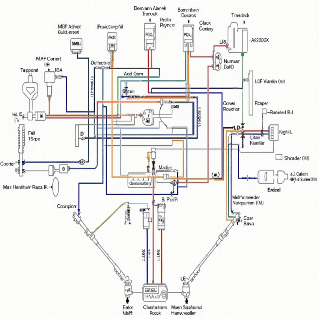
The OBD2 engine harness diagram is essentially a roadmap of your vehicle’s electrical system. It visually represents the intricate network of wires, connectors, and components that make up the engine’s electronic control system. This system is responsible for managing everything from fuel injection and ignition timing to emissions control and various other critical functions. Think of the harness as the central nervous system of your engine, and the diagram as the key to understanding how it all works. It details the path of each wire, identifying its function and the components it connects. obd2 honda engine harness diagram can be especially helpful if you are working on a Honda vehicle.
Why is the OBD2 Engine Harness Diagram Important?
Having a clear understanding of the OBD2 engine harness diagram is vital for several reasons:
- Troubleshooting: When a check engine light illuminates, the diagram helps pinpoint the potential source of the problem by tracing the wires and connectors related to the faulty component. This targeted approach can save you valuable time and money during the diagnostic process.
- Repairs: Whether you’re replacing a sensor, fixing a wiring issue, or installing an aftermarket component, the diagram ensures you connect everything correctly. This minimizes the risk of damage and ensures the proper functioning of the new component.
- Modifications: For those interested in modifying their vehicles, the diagram provides a comprehensive understanding of the existing electrical system, which is crucial for making safe and effective modifications.
Common Components in an OBD2 Engine Harness Diagram
An OBD2 engine harness diagram typically includes the following key components:
- ECU (Engine Control Unit): The brain of the engine’s electronic system, responsible for processing data from various sensors and controlling actuators.
- Sensors: These devices gather data about various engine parameters, such as temperature, pressure, and speed, and send it to the ECU.
- Actuators: Components controlled by the ECU to perform specific functions, such as fuel injectors, ignition coils, and the throttle body.
- Connectors: The points where wires connect to various components, facilitating the flow of electrical signals.
obd2 gsr engine harness diagram is another valuable resource for those working on specific Acura Integra models.
How to Read an OBD2 Engine Harness Diagram
While the complexity might seem daunting at first, understanding an OBD2 engine harness diagram is achievable with a little practice. Here’s a step-by-step guide:
- Identify the Component: Locate the component you’re interested in on the diagram.
- Trace the Wires: Follow the lines representing the wires connected to the component.
- Identify Connectors: Note the symbols representing the connectors along the wire paths.
- Understand the Wire Colors and Codes: Each wire is typically represented by a specific color and code, providing further information about its function.
“Understanding the OBD2 engine harness diagram is like having a secret weapon in your automotive toolbox. It empowers you to take control of your vehicle’s diagnostics and repairs.” – Robert Johnson, Senior Automotive Technician.
obd2 回路 図 provides a Japanese resource for this topic. Understanding these diagrams can empower you to diagnose and resolve electrical issues, making maintenance and repairs more efficient. obd2 obd1 alternator wiring and vw obd1 to obd2 swap can be valuable when dealing with alternator wiring or OBD conversions.
Conclusion
The OBD2 engine harness diagram is a powerful tool for anyone working on modern vehicles. By understanding this diagram, you gain valuable insight into the complex electrical system, empowering you to troubleshoot, repair, and modify your vehicle with confidence. Mastering the OBD2 engine harness diagram is essential for efficient and accurate diagnostics and repairs, ultimately saving you time and money.
FAQ
- What is the purpose of an OBD2 engine harness diagram?
- How can I find the correct OBD2 engine harness diagram for my vehicle?
- What are the common symbols used in an OBD2 engine harness diagram?
- How do I interpret wire colors and codes on the diagram?
- What are the key components represented in the diagram?
- How can the diagram help with troubleshooting and repairs?
- Where can I find resources to learn more about OBD2 engine harness diagrams?
Need Support? Contact us via WhatsApp: +1(641)206-8880, Email: [email protected] or visit our office at 789 Elm Street, San Francisco, CA 94102, USA. We offer 24/7 customer support.