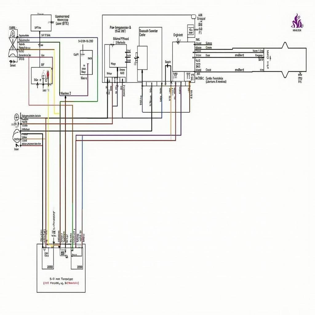
The OBD2 GSR engine harness diagram is a crucial resource for anyone working on a Honda Integra GSR. This diagram provides a visual representation of the electrical system, allowing mechanics and enthusiasts to diagnose issues, install aftermarket components, and understand the intricate workings of their vehicle’s engine.
A thorough understanding of the OBD2 GSR engine harness diagram can save you time and frustration when troubleshooting electrical problems. Whether you’re dealing with a faulty sensor, a blown fuse, or a more complex wiring issue, this diagram provides the roadmap you need to navigate the electrical system. It helps pinpoint the location of specific components and trace the flow of electricity, making it easier to identify the root cause of a problem.
Decoding the OBD2 GSR Engine Harness Diagram
The diagram itself can appear overwhelming at first glance, a complex network of lines, symbols, and connectors. However, with a little guidance, you can easily decipher this valuable resource. The diagram is typically organized by functional areas, such as the engine control module (ECM), the fuel injection system, and the ignition system. Each component is represented by a symbol, and the connecting wires are shown as lines. These lines are often color-coded to correspond to the actual wire colors in the harness.
 OBD2 GSR Engine Harness Diagram Overview
Why is the OBD2 GSR Wiring Harness Diagram Important?
The OBD2 GSR wiring harness diagram is essential for several reasons. Firstly, it helps in diagnosing electrical problems. By tracing the wires and identifying the components connected to them, you can quickly pinpoint the source of the issue. Secondly, it’s invaluable when installing aftermarket components. Knowing the correct wiring connections is crucial for the proper functioning of these components and prevents damage to the vehicle’s electrical system. Lastly, understanding the wiring harness diagram helps in understanding the overall functioning of the engine’s electrical system.
How to Use the OBD2 GSR Engine Harness Diagram Effectively?
Using the diagram effectively involves a few key steps. First, identify the component you’re working on. Locate its corresponding symbol on the diagram. Next, trace the wires connected to that component. Note the color codes and the connectors they lead to. This will help you understand how the component is integrated into the electrical system. Finally, consult the diagram legend to understand the meaning of various symbols and abbreviations.
Common Issues and Troubleshooting with the OBD2 GSR Harness Diagram
Common issues related to the GSR engine harness can include faulty sensors, broken wires, and corroded connectors. Using the obd2 harness diagram can help you locate the problematic area and identify the correct repair procedure. For example, if you encounter an is09141 obd2 code, the diagram can help you trace the related circuitry.
Expert Insight: “A common mistake is neglecting the importance of proper grounding. The engine harness diagram clearly shows the grounding points, and ensuring these are clean and secure is crucial for the entire electrical system’s stability,” says John Miller, a veteran automotive electrician.
Finding the Right OBD2 GSR Engine Harness Diagram
Finding the correct diagram for your specific GSR model year is essential. Slight variations can exist between different years, so using the wrong diagram can lead to incorrect diagnoses and repairs. Resources like service manuals and online databases are good places to find accurate diagrams.
“Always double-check the wire colors and connector pinouts before making any connections or disconnections. This simple step can save you from costly mistakes,” advises Sarah Johnson, an experienced automotive technician.
The obd2 gsr wiring harness diagram and obd2 wire diagram are essential resources for anyone working on a Honda Integra GSR. By understanding how to use these diagrams effectively, you can diagnose problems, install aftermarket components, and maintain the health of your vehicle’s electrical system.
In conclusion, the OBD2 GSR engine harness diagram is an indispensable tool for anyone working on this specific vehicle. It provides a clear and concise visual representation of the intricate electrical system, allowing for accurate diagnosis and repair of electrical issues. Understanding this diagram is key to keeping your GSR running smoothly.
FAQ
- Where can I find a reliable OBD2 GSR engine harness diagram? Reliable sources include official service manuals and reputable online databases.
- What are the common issues related to the GSR engine harness? Common problems include faulty sensors, broken wires, and corroded connectors.
- How can I use the diagram to diagnose electrical problems? Trace the wires and identify the components connected to them to pinpoint the source of the issue.
- Why is it important to use the correct diagram for my specific model year? Variations exist between different model years, so using the wrong diagram can lead to incorrect diagnoses and repairs.
- What should I do before making any connections or disconnections in the harness? Always double-check the wire colors and connector pinouts.
If you need assistance, please contact WhatsApp: +1(641)206-8880, Email: cardiagtechworkshop@gmail.com. We have a 24/7 customer support team.

