The OBD2 interface circuit diagram is essential for anyone working with vehicle diagnostics. It provides a roadmap to the communication network within your car, allowing you to understand how your OBD2 scanner interacts with various vehicle systems. This article delves into the intricacies of the OBD2 interface, exploring its components, functionality, and practical applications.
An OBD2 interface, also known as a diagnostic port, is the gateway to a vehicle’s internal network. It allows external devices, such as OBD2 scanners, to communicate with the various electronic control units (ECUs) within the car. This communication enables retrieving diagnostic trouble codes (DTCs), monitoring real-time data, and performing various tests. Understanding the obd2 interface circuit diagram is crucial for effective vehicle diagnostics and troubleshooting. For example, knowing the pinout configuration can help identify communication issues.
Decoding the OBD2 Interface Circuit Diagram
The standardized OBD2 connector, commonly referred to as the J1962 connector, consists of 16 pins. Each pin has a specific function, contributing to the overall communication and power supply. The diagram illustrates the connection between these pins and the various components within the vehicle’s network.
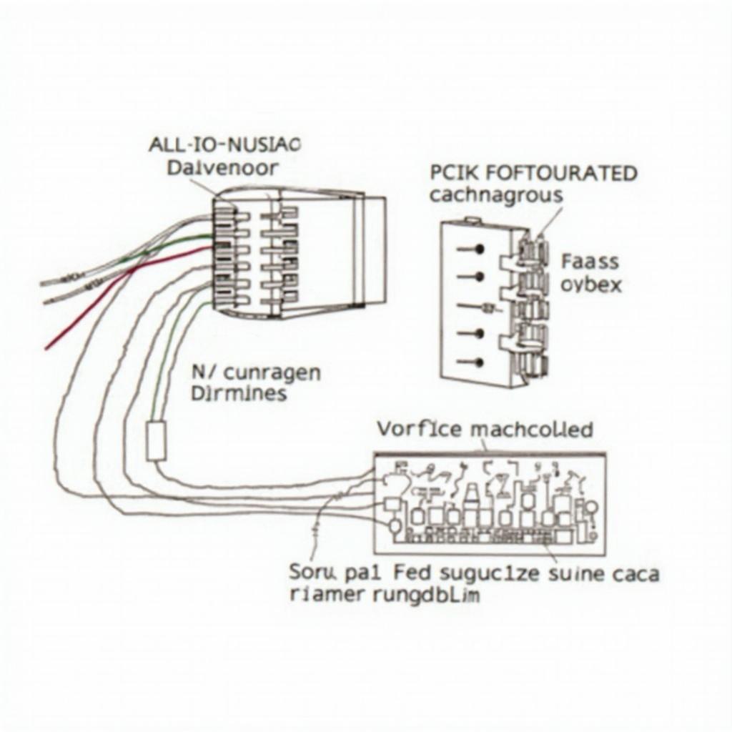 OBD2 Interface Circuit Diagram Overview
Key Components of the OBD2 Interface
- Power Supply (Pin 16): Provides battery power to the connected diagnostic tool. This ensures the scanner can operate independently without drawing power from other vehicle systems.
- Ground (Pin 4 & 5): Establishes a common ground for the circuit, ensuring stable voltage levels and preventing electrical interference.
- Communication Lines (Various Pins): These pins facilitate communication between the scanner and the ECUs. Different protocols, such as CAN, J1850, and ISO 9141-2, use specific pin combinations for data transmission. Understanding these protocols is vital for interpreting the data received from the vehicle.
Practical Applications of the OBD2 Interface Circuit Diagram
Understanding the honda obd2 8 pinout can be immensely helpful in various scenarios, ranging from basic diagnostics to advanced troubleshooting.
- Troubleshooting Communication Issues: If your scanner fails to connect, the diagram can help you identify potential issues with the connector or wiring. Checking the continuity of the power and ground lines is a good starting point.
- Identifying Protocol Compatibility: By knowing the pin configuration for each protocol, you can ensure that your scanner supports the protocol used by your vehicle.
- Customizing Diagnostic Tools: For advanced users, the circuit diagram allows for the development of custom diagnostic tools and interfaces tailored to specific needs. This might involve connecting to specific ECUs or monitoring specific data streams.
Common Questions about OBD2 Interface Circuit Diagrams
What are the different communication protocols used by OBD2? OBD2 utilizes several communication protocols, including CAN, J1850, and ISO 9141-2. These protocols define how data is transmitted between the scanner and the vehicle’s ECUs.
How can I identify the protocol used by my car? You can determine your car’s protocol by checking the vehicle’s documentation or using an OBD2 scanner that automatically detects the protocol. Knowing the 95 mustang gt obd2 port is essential for effective diagnostics.
Conclusion
The obd2 interface circuit diagram is a vital tool for anyone involved in vehicle diagnostics. It provides a fundamental understanding of how your OBD2 scanner interacts with your car’s systems, enabling efficient troubleshooting and informed decision-making. Mastering the obd2 interface circuit diagram empowers you to take control of your vehicle’s diagnostics, saving time and money. You might even find the 2013 chevy silverado 2500 obd2 fuse information helpful as well.
FAQs
- What is the purpose of the OBD2 interface?
- How many pins does the OBD2 connector have?
- What are the key components of the OBD2 interface circuit?
- How can the OBD2 interface diagram help with troubleshooting?
- Where can I find a reliable OBD2 interface circuit diagram for my specific vehicle?
- What is the idatalink maestro rr obd2 1998 mustang?
- Where can I find information about a 36 pin obd2 ic?
For support contact WhatsApp: +1(641)206-8880, Email: [email protected] or 789 Elm Street, San Francisco, CA 94102, USA. We have a 24/7 customer support team.