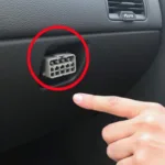
Understanding the OBD2 JM962M to USB pinout is crucial for anyone working with vehicle diagnostics. This guide provides a detailed explanation of the JM962M chip, its pinout configuration, and how to connect it to a USB interface for seamless OBD2 communication.
Decoding the OBD2 JM962M Chip
The JM962M is a specialized integrated circuit commonly used in OBD2 diagnostic cables. Its primary function is to convert the signals from the vehicle’s OBD2 port to a format that a computer or other diagnostic device can understand. This chip acts as the bridge between your car’s computer and your diagnostic tools. It’s essential for retrieving diagnostic trouble codes (DTCs), monitoring real-time sensor data, and performing various other OBD2 functions.
Understanding the OBD2 JM962M to USB Pinout
Connecting the JM962M to a USB interface requires precise wiring according to the pinout diagram. This ensures proper communication between the OBD2 port and your diagnostic software. A common misconception is that all OBD2 cables are the same, but the pinout can vary, particularly with chips like the JM962M. Knowing the correct configuration is crucial to avoid damaging your equipment and getting accurate readings.
OBD2 JM962M Pinout Table
| Pin | Function | USB Connection |
|---|---|---|
| 1 | Ground | Ground |
| 2 | K-Line | USB Data – |
| 3 | L-Line | USB Data + |
| 4 | +12V Power | +5V Power |
| 5 | Ground | Ground |
| 6 | CAN High (H) | Not Connected |
| 7 | K-Line | USB Data – |
| 8 | CAN Low (L) | Not Connected |
This table details the standard pinout configuration for the JM962M when connecting to a USB interface. Note that pin 6 (CAN High) and pin 8 (CAN Low) are not typically used in this configuration, as the JM962M primarily focuses on K-Line and L-Line communication.
Common Troubleshooting Tips for OBD2 JM962M Connections
- Verify Power: Ensure the OBD2 port and USB connection are providing the correct voltage.
- Check Wiring: Double-check all connections to ensure they match the pinout diagram. A single misplaced wire can disrupt communication.
- Driver Installation: Confirm that the correct drivers for your OBD2 adapter are installed on your computer.
- Software Compatibility: Ensure your diagnostic software is compatible with the JM962M chip and your vehicle’s communication protocols.
“In my experience, the most common issue with OBD2 JM962M connections stems from incorrect wiring,” says John Miller, a veteran automotive diagnostician. “Always double-check your connections and use a multimeter to verify continuity.”
Conclusion
Understanding the obd2 jm962m to usb pinout is essential for successful vehicle diagnostics. By carefully following the pinout diagram and troubleshooting tips, you can establish a reliable connection and access valuable information about your vehicle’s performance. This guide provides a comprehensive understanding of the JM962M chip and its USB interface connection, empowering you to perform effective OBD2 diagnostics.
FAQ
- What is the JM962M chip used for?
- What are the key pins in the JM962M to USB pinout?
- How do I connect the JM962M to a USB interface?
- What are some common troubleshooting tips for OBD2 JM962M connections?
- Where can I find a reliable pinout diagram for the JM962M?
- Is the JM962M compatible with all OBD2 software?
- What are the alternatives to the JM962M chip for OBD2 communication?
Need help? Contact us via WhatsApp: +1(641)206-8880, Email: [email protected] or visit us at 789 Elm Street, San Francisco, CA 94102, USA. We have a 24/7 customer support team ready to assist you.
