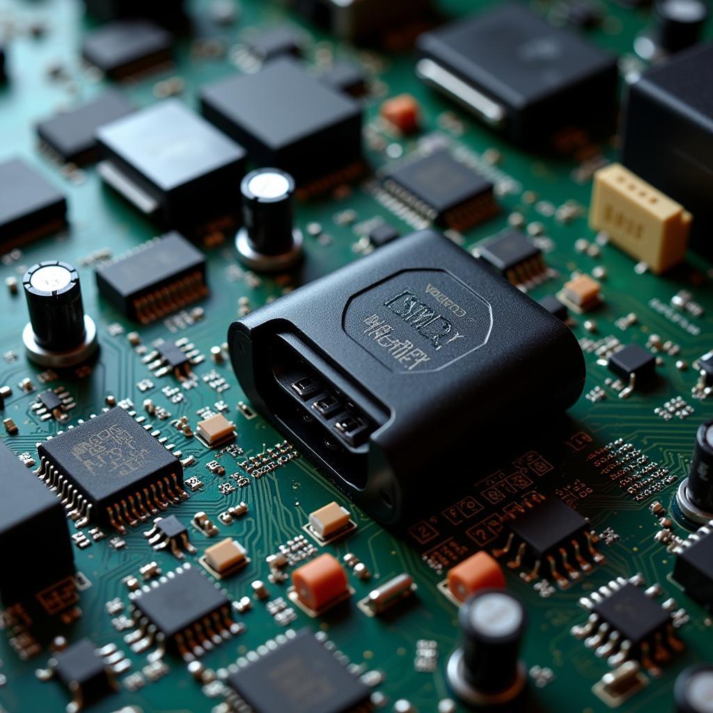
The OBD2 scanner, a staple tool for automotive enthusiasts and professionals, unlocks a vehicle’s onboard computer to reveal valuable diagnostic information. But have you ever wondered about the intricate network of circuits that power this communication? This article delves into the fascinating world of the OBD2 scanner circuit diagram, uncovering its components and functionality.
Decoding the Circuitry: A Breakdown
At its core, an OBD2 scanner circuit diagram maps out the electrical connections that enable communication between the scanner and the vehicle’s Electronic Control Unit (ECU). This diagram is essentially a roadmap, guiding you through the flow of data and the functions of each component.
Key Components and Their Roles:
-
Microcontroller: The brain of the operation, this integrated circuit processes data received from the vehicle’s ECU and translates it into a readable format for the user interface.
-
Memory: This component stores the scanner’s firmware, which dictates its operating instructions and data processing capabilities.
-
Communication Interface: This crucial part, often utilizing the CAN (Controller Area Network) protocol, facilitates the exchange of data between the scanner and the ECU.
-
Power Supply: Typically drawing power from the vehicle’s OBD2 port, this circuit regulates and supplies the necessary voltage for all components.
-
Input/Output Ports: These connections allow for user interaction with the scanner (e.g., buttons, display screen) and potential expansions like data logging capabilities.
The Importance of Understanding the Circuit Diagram
A firm grasp of the OBD2 scanner circuit diagram offers numerous benefits:
-
Troubleshooting: When issues arise, the diagram serves as a diagnostic tool to pinpoint the source of the problem, whether it’s a faulty connection or a malfunctioning component.
-
Repair and Modification: For tech-savvy users, the diagram provides the necessary blueprint for advanced repairs or even modifications to enhance the scanner’s functionalities.
-
Deeper Understanding: Beyond practical applications, understanding the circuitry deepens your appreciation for the sophisticated technology that empowers modern vehicle diagnostics.
Common Questions About OBD2 Scanner Circuits
Q: Can I modify the circuit diagram to customize my scanner?
A: While possible, modifications require advanced technical knowledge and should only be attempted by experienced individuals. Incorrect alterations can potentially damage the scanner or the vehicle’s ECU.
Q: Where can I find a reliable OBD2 scanner circuit diagram?
A: Reputable manufacturers often provide circuit diagrams in their product documentation. Online resources and forums dedicated to automotive electronics can also be valuable sources of information.
Conclusion
The OBD2 scanner circuit diagram, while seemingly complex at first glance, is the key to unlocking a deeper understanding of this essential diagnostic tool. By familiarizing yourself with its components and connections, you gain valuable insights into the inner workings of your scanner and empower yourself to maximize its potential.
Remember, whether you’re a seasoned mechanic or a car enthusiast eager to delve into diagnostics, the circuit diagram is your roadmap to navigating the fascinating world of OBD2 scanners.


