The OBD2 serial cable pinout is the key to unlocking the diagnostic power of your vehicle’s onboard computer. This article will delve into the intricacies of the OBD2 serial cable pinout, providing a comprehensive guide for both car enthusiasts and professional mechanics. We’ll cover everything from basic pin identification to advanced troubleshooting techniques. sct obd2 cable
Decoding the OBD2 Serial Cable Pinout
Understanding the OBD2 serial cable pinout is essential for establishing communication with your vehicle’s ECU. Each pin on the connector has a specific function, ranging from power supply to data transmission. Misinterpreting the pinout can lead to communication failures or even damage to your vehicle’s diagnostic system.
OBD2 Pinout: A Detailed Breakdown
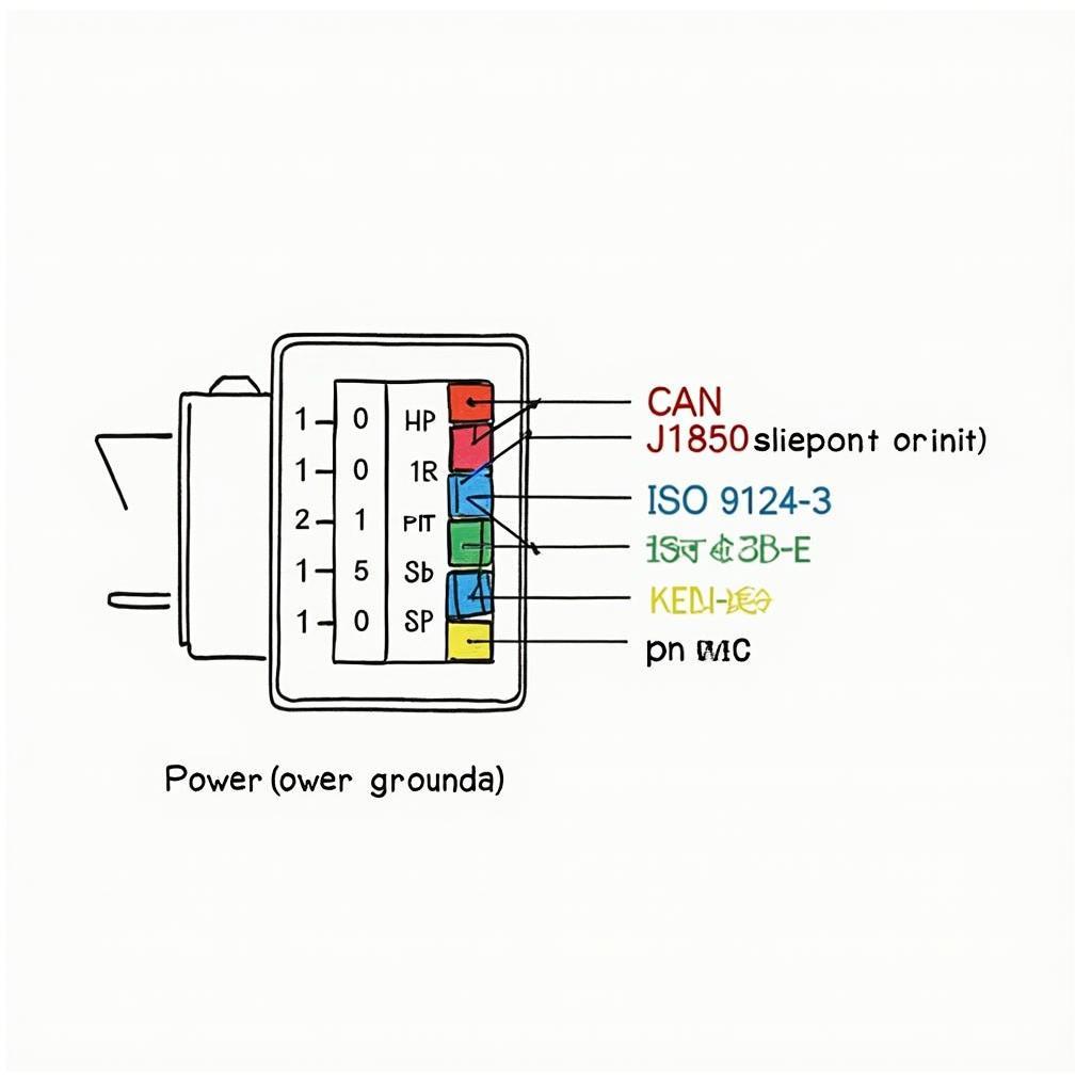
The standard OBD2 connector has 16 pins, each with a designated purpose. Let’s explore the function of each pin:
- Pin 1: Not Used
- Pin 2: J1850 Bus+
- Pin 3: Not Used
- Pin 4: Chassis Ground
- Pin 5: Signal Ground
- Pin 6: CAN High (J-2284)
- Pin 7: ISO 9141-2 K-Line
- Pin 8: Not Used
- Pin 9: Not Used
- Pin 10: J1850 Bus-
- Pin 11: Not Used
- Pin 12: Not Used
- Pin 13: Not Used
- Pin 14: CAN Low (J-2284)
- Pin 15: ISO 9141-2 L-Line
- Pin 16: Battery Power
This pinout is crucial when making your own obd2 to db9 cable.
Why is the OBD2 Serial Cable Pinout Important?
The OBD2 pinout is the roadmap to accessing your vehicle’s diagnostic data. Understanding this pinout allows you to:
- Diagnose vehicle problems: By connecting a scan tool to the correct pins, you can retrieve diagnostic trouble codes (DTCs) and other valuable data that pinpoint the source of vehicle malfunctions.
- Monitor vehicle performance: The OBD2 pinout enables real-time monitoring of various engine parameters, such as speed, RPM, coolant temperature, and fuel consumption.
- Customize vehicle settings: Certain parameters can be adjusted through the OBD2 port, allowing you to personalize your vehicle’s performance.
What are the common communication protocols used with OBD2? The most common protocols are CAN, J1850, and ISO 9141-2. Each protocol uses different pins on the OBD2 connector.
What is the difference between signal ground and chassis ground? Signal ground (pin 5) is the reference point for the voltage signals used in data communication. Chassis ground (pin 4) provides a direct connection to the vehicle’s chassis, ensuring a stable electrical reference point.
bluetooth obd2 bafx o2 bank sensor can be really useful.
John Smith, a seasoned automotive diagnostician, emphasizes the importance of understanding the OBD2 pinout: “Knowing the pinout is like knowing the language your car speaks. It allows you to communicate effectively with the vehicle’s computer and get to the root of any problem.”
Building Your Own OBD2 Cable
how to make a obd2 usb cable can be a rewarding project.
obd2 to db9 cable is another popular option.
Jane Doe, an electronics engineer specializing in automotive diagnostics, adds: “Building your own OBD2 cable gives you complete control over the quality and functionality of your diagnostic setup. It’s a valuable skill for any car enthusiast.”
OBD2 Serial Cable Pinout: Conclusion
The OBD2 serial cable pinout is more than just a collection of wires and pins; it’s the gateway to understanding your vehicle’s inner workings. Whether you’re a professional mechanic or a DIY enthusiast, a deep understanding of the OBD2 pinout is essential for effective vehicle diagnostics and maintenance. This knowledge empowers you to troubleshoot problems, monitor performance, and unlock the full potential of your OBD2 scanner.
FAQ
- What is the purpose of pin 16 on the OBD2 connector? Pin 16 provides battery power to the diagnostic tool.
- What are the different communication protocols used in OBD2? The common protocols are CAN, J1850, and ISO 9141-2.
- Can I damage my car by miswiring the OBD2 connector? Yes, incorrect wiring can damage the vehicle’s diagnostic system.
- Where can I find a reliable OBD2 pinout diagram? Refer to reputable automotive resources or the vehicle’s service manual.
- What tools do I need to build my own OBD2 cable? You’ll need an OBD2 connector, appropriate wiring, soldering iron, and other basic tools.
- Are all OBD2 connectors the same? Yes, physically they are the same, but the communication protocols used can differ depending on the vehicle’s make and model.
- How do I choose the right OBD2 cable for my vehicle? Consider the communication protocol used by your vehicle and the type of diagnostic tool you plan to use.
For further assistance, please contact us via WhatsApp: +1(641)206-8880, Email: [email protected] or visit our office at 789 Elm Street, San Francisco, CA 94102, USA. Our customer support team is available 24/7.


