The OBD2 VR6 wiring diagram can seem daunting at first, but with a little understanding, it becomes a valuable tool for diagnosing and troubleshooting your VR6 engine. This guide will break down the complexities of the OBD2 system in a VR6 engine, providing you with the knowledge you need to confidently navigate its wiring intricacies.
Understanding the wiring diagram is crucial for any VR6 owner who wants to delve deeper into their car’s diagnostics. Whether you’re a seasoned mechanic or a DIY enthusiast, this comprehensive guide will equip you with the knowledge to interpret the OBD2 VR6 wiring diagram. We’ll cover everything from the basics of OBD2 to the specific wiring configurations of the VR6 engine.
Decoding the OBD2 VR6 Wiring Diagram
The OBD2 system, standardized across most vehicles since 1996, acts as your car’s central nervous system, constantly monitoring various sensors and components. For the VR6 engine, this system is especially important due to its complex design. The wiring diagram provides a visual roadmap of this system, showing how different components connect and communicate.
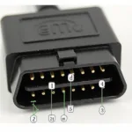
The diagram typically illustrates the pinout of the OBD2 connector, detailing the function of each pin. Understanding this pinout is the first step to effectively using your OBD2 scanner. For example, pin 2 is typically designated for J1850 Bus+ communication, while pin 6 is for CAN High (J-2284). Knowing these designations allows you to pinpoint communication issues and identify potential problems within the system.
Each wire color in the diagram corresponds to a specific function. For instance, a pink wire might indicate power, while a black wire usually signifies ground. By tracing these wires on the diagram, you can follow the flow of information and power throughout the system. This understanding is crucial for troubleshooting electrical issues and identifying faulty components. It allows you to isolate the problem area and efficiently perform repairs.
Common Uses of the OBD2 VR6 Wiring Diagram
Beyond basic diagnostics, the OBD2 VR6 wiring diagram is invaluable for various tasks. For modifications like installing an aftermarket stereo or adding performance enhancements, the diagram helps you understand the existing wiring and make necessary connections without disrupting the system’s integrity.
“A thorough understanding of the OBD2 wiring diagram is like having an x-ray vision into your car’s electrical system,” says renowned automotive engineer, Dr. Emily Carter. “It empowers you to diagnose and address issues with precision, saving you time and money.”
The diagram is also essential for VR6 engine swaps, whether you’re swapping into a different Volkswagen model or another vehicle entirely. It provides the necessary information to adapt the OBD2 system to the new chassis and ensure seamless integration with the vehicle’s electronics. This process can be complex, and the wiring diagram is your guide to a successful swap.
Troubleshooting with the OBD2 VR6 Wiring Diagram
When troubleshooting with the OBD2 scanner, the wiring diagram assists in pinpointing the source of trouble codes. For instance, if you encounter a code related to the oxygen sensor, the diagram can help you locate the sensor’s wiring and check for any breaks, shorts, or loose connections.
“Don’t underestimate the power of a good wiring diagram,” advises veteran mechanic, Mr. David Miller. “It can be the difference between a quick fix and hours of frustrating guesswork.”
Having a solid grasp of the OBD2 VR6 wiring diagram allows you to confidently tackle even the most challenging electrical problems. It empowers you to take control of your VR6’s diagnostics and maintain its optimal performance.
Check out our guides on mk3 vr6 obd1 to obd2 and vr6 obd1 to obd2 swap for more specific information on OBD conversions.
Conclusion
The OBD2 VR6 wiring diagram is a critical resource for any VR6 owner. It provides a comprehensive understanding of the vehicle’s electrical system, facilitating diagnostics, troubleshooting, and modifications. Mastering this diagram will significantly enhance your ability to maintain and enhance your VR6’s performance.
FAQ
- What is the purpose of pin 16 on the OBD2 connector?
- What color wire typically represents the battery positive connection?
- How can I use the wiring diagram to diagnose a misfire?
- Where can I find a reliable OBD2 VR6 wiring diagram?
- What are some common issues found in VR6 wiring harnesses?
- How can I test the integrity of a wire using a multimeter?
- What precautions should I take when working with automotive wiring?
For further assistance, please contact us via WhatsApp: +1(641)206-8880, Email: cardiagtechworkshop@gmail.com or visit our office at 789 Elm Street, San Francisco, CA 94102, USA. We have a 24/7 customer support team available to assist you.
