The OBD2 port, often found under your car’s dashboard, is a gateway to your vehicle’s soul (or at least, its engine control unit). But understanding the language it speaks – communicated through an intricate network of wires detailed in an OBD2 wire diagram – can be daunting for the uninitiated. This guide will demystify the world of OBD2 wiring, providing you with the knowledge to confidently diagnose car troubles and even tackle some DIY repairs.
What Exactly is an OBD2 Wire Diagram?
An OBD2 wire diagram is essentially a roadmap for your car’s onboard diagnostic system. It illustrates the pathways of individual wires connecting the OBD2 port to various sensors, actuators, and the ECU (Engine Control Unit). This visual representation decodes the electrical signals traveling through the system, enabling you to:
- Identify the function of each wire: Each wire color in an OBD2 system corresponds to a specific signal or function. The diagram helps you decipher these color codes, pinpointing wires responsible for transmitting data from the oxygen sensor, throttle position sensor, and countless others.
- Diagnose wiring faults: A broken wire, loose connection, or short circuit can throw your car’s systems into disarray. With an OBD2 wire diagram, you can trace the path of suspect wires, identifying and rectifying the root cause of electrical gremlins.
- Install aftermarket devices: Adding gadgets like a remote starter or performance chip often requires tapping into your car’s OBD2 system. A wiring diagram becomes your guide, ensuring you make the right connections without risking damage to your vehicle’s electronics.
Deciphering the Code: Standard OBD2 Pinout
While specific wire colors might vary between manufacturers, the OBD2 port itself follows a standardized pinout configuration. Familiarizing yourself with this layout is crucial for understanding any OBD2 wire diagram:
- Pin 1 & 2: Reserved for manufacturer-specific use.
- Pin 3: Usually unused but can be designated for manufacturer-specific purposes.
- Pin 4: Chassis Ground – provides a grounding point for the system.
- Pin 5: Signal Ground – a reference point for voltage measurements in the system.
- Pin 6: CAN High (Controller Area Network) – used for high-speed data communication.
- Pin 7: K-Line – an older communication protocol, mostly phased out in modern vehicles.
- Pin 8: CAN Low – complements Pin 6 for high-speed data transmission.
- Pin 9: Reserved for manufacturer-specific use.
- Pin 10: J1850 Bus+ – another communication protocol used primarily by Ford vehicles.
- Pin 11: Reserved for manufacturer-specific use.
- Pin 12: Reserved for manufacturer-specific use.
- Pin 13: Reserved for manufacturer-specific use.
- Pin 14: CAN High (for secondary data bus if equipped).
- Pin 15: L-Line – a communication protocol mainly used by European vehicles.
- Pin 16: Battery Positive – provides constant power to the OBD2 port.
Why You Need an OBD2 Wire Diagram
You might be wondering, “Why bother with a diagram when I can just plug in my OBD2 scanner and read the codes?” While scanners are invaluable for retrieving diagnostic trouble codes (DTCs), they only offer a glimpse into the bigger picture. An OBD2 wire diagram, on the other hand, empowers you to:
-
Pinpoint intermittent issues: Sometimes, a problem might not be severe enough to trigger a DTC, or it could be intermittent, disappearing before you can diagnose it. By analyzing the wiring diagram, you can proactively check specific components or connections related to the symptoms, even without an active fault code.
-
Troubleshoot communication errors: Encountering a “link error” or “no communication” message on your scanner? This usually signifies a problem within the OBD2 wiring itself. The diagram allows you to test continuity, ensuring signals are flowing correctly between the port, ECU, and relevant sensors.
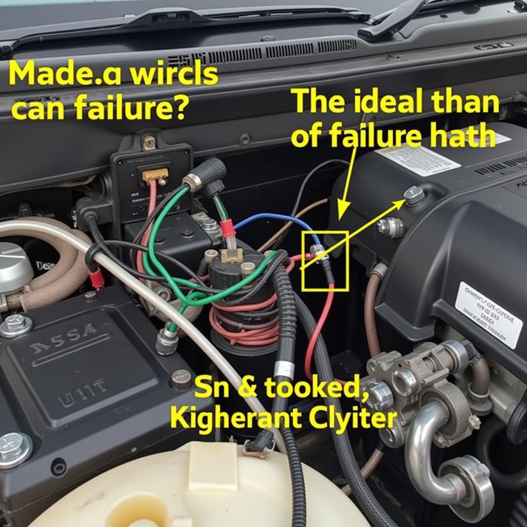
 Close-up View of an OBD2 Wiring Harness
- Gain a deeper understanding of your vehicle: Going beyond simply reading codes, an OBD2 wire diagram allows you to grasp the intricate workings of your car’s various systems. This knowledge can be invaluable for preventative maintenance, performance tuning, and even just satisfying your inner automotive enthusiast.
Finding the Right OBD2 Wire Diagram
Locating the specific OBD2 wire diagram for your vehicle is crucial, as they can vary significantly between makes, models, and even model years. Here are some reliable sources:
-
Vehicle Repair Manuals: Considered the holy grail of automotive information, factory repair manuals often include detailed wiring diagrams. While they might seem expensive upfront, the wealth of knowledge they provide is invaluable for any DIY mechanic.
-
Online Databases: Several reputable websites offer access to extensive automotive wiring diagrams. Websites like OBDFree can provide access to these resources, often for free or a nominal fee.
-
Automotive Forums: Online communities dedicated to specific car brands or models can be treasure troves of information. Many experienced members readily share their knowledge and might even have access to rare wiring diagrams.
A word of caution: Always verify the accuracy of any diagram you obtain from unofficial sources. Cross-referencing information with multiple sources can help ensure you’re working with reliable data.
Navigating the World of OBD2 Wiring
While the intricate web of lines and symbols in an OBD2 wire diagram might seem intimidating at first glance, with a little patience and guidance, you can decipher its secrets. Armed with this knowledge, the OBD2 system transforms from a black box into a powerful tool, putting you in the driver’s seat of your car’s diagnostics and repairs.
Remember: Always disconnect the negative battery terminal before working on any electrical components to prevent accidental shorts or damage to your vehicle’s electronics. When in doubt, consult a professional mechanic for assistance.
FAQs About OBD2 Wire Diagrams
1. Can I use a universal OBD2 wire diagram?
While universal diagrams provide a general overview of the OBD2 system, they are not a substitute for a vehicle-specific diagram. Utilizing a diagram that doesn’t match your car’s exact make, model, and year can lead to misinterpretations and potentially damage your vehicle’s electronics.
2. What is the significance of wire colors in an OBD2 diagram?
Wire colors in an OBD2 diagram are not merely decorative; they follow a standardized code that identifies the function of each wire. For instance, a pink wire often indicates power to fuel injectors, while a yellow wire might signify communication with the airbag control module.
3. My OBD2 scanner isn’t communicating with my car. Can a wiring diagram help?
Absolutely! A wiring diagram can help you diagnose communication errors by enabling you to check for continuity in the wires connecting your OBD2 port to the ECU and other relevant components. This allows you to identify potential breaks, shorts, or loose connections that might be hindering communication.
4. I’m installing an aftermarket device that connects to the OBD2 port. Do I need a wiring diagram?
It’s highly recommended. While some aftermarket devices offer plug-and-play installation, others require tapping into specific wires within the OBD2 system. A wiring diagram ensures you make the correct connections, avoiding potential damage to your vehicle’s electronics and ensuring proper functionality of the device.
5. Where can I get my car’s factory repair manual, which includes the OBD2 wire diagram?
You can usually purchase factory repair manuals online through reputable sources like manufacturer websites, automotive book retailers, or even online auction sites. Additionally, some public libraries might have collections of these manuals available for borrowing.
Need Further Assistance?
Navigating the intricacies of your car’s electrical system can be challenging. If you’re facing a particularly perplexing issue or simply need an extra hand, don’t hesitate to reach out to our team of automotive experts. We’re available 24/7 via WhatsApp at +1(641)206-8880 or email at [email protected]. We’re always happy to help you get back on the road and confident in your car’s performance.
For information regarding specific vehicles and common OBD2 issues, explore our extensive library of resources on OBDFree. You can find detailed guides like our articles on the 1999 Lincoln Towncar OBD2 Fuse, H23 OBD2 Distributor Wiring, and troubleshooting the OBD2 Connector Location on a 2017 Volvo XC90er S. We also offer comprehensive information on the OBD2 GSR Wiring Harness Diagram and the 1JZGTE OBD2 Port.

