Understanding your OBD2 pin connector label is crucial for effective vehicle diagnostics. Whether you’re a seasoned mechanic or a DIY enthusiast, this guide will unravel the mysteries of the OBD2 port and its pinout, empowering you to troubleshoot car problems with confidence. We’ll explore the function of each pin, common issues, and how to use this knowledge to keep your vehicle running smoothly.
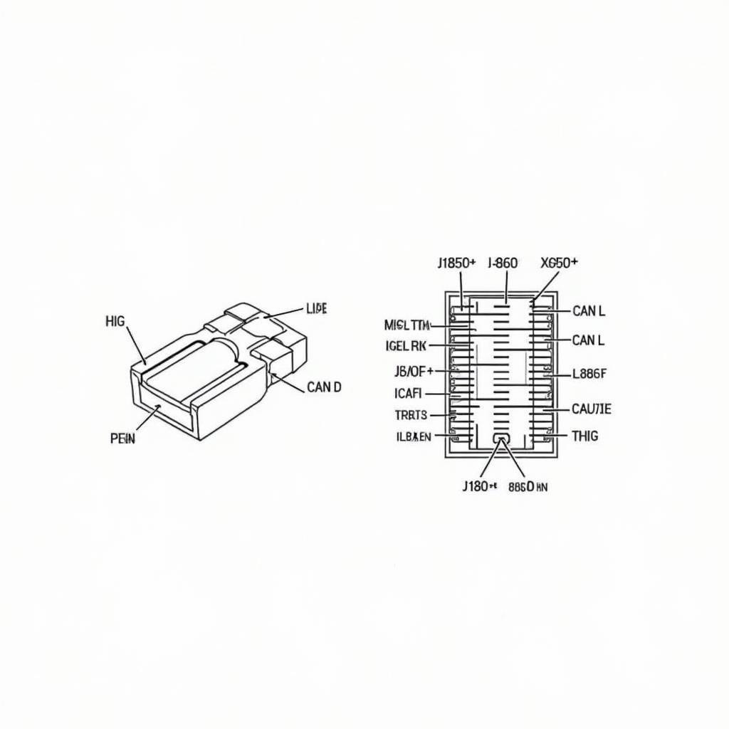
 OBD2 Connector Pinout Diagram Showing Pin Numbers and Functions
The OBD2, or On-Board Diagnostics II, port is your vehicle’s gateway to its internal systems. This standardized 16-pin connector provides access to a wealth of diagnostic data, allowing you to identify and address a range of issues. By understanding the pin connector label obd2, you can effectively use a scan tool to interpret trouble codes, monitor sensor data, and even perform specific tests. This knowledge can save you time and money on repairs, and give you a deeper understanding of your vehicle’s health. Did you know that the location of the OBD2 port can vary slightly between vehicle makes and models? For instance, you can find the OBD2 port location for a 1997 F350 by checking our dedicated guide.
What Does Each Pin on the OBD2 Connector Do?
Each pin on the OBD2 connector has a specific function, often related to different communication protocols or power supply. Some pins are dedicated to specific manufacturers, while others are standardized across all vehicle makes and models. Understanding these functions is essential for accurate diagnosis.
- Pin 1: Not always used, but sometimes for manufacturer-specific diagnostics.
- Pin 2: J1850 Bus+ (used by Ford and other manufacturers).
- Pin 3: Not always used, but sometimes for manufacturer-specific diagnostics.
- Pin 4: Chassis Ground.
- Pin 5: Signal Ground.
- Pin 6: CAN High (Controller Area Network).
- Pin 7: ISO 9141-2 K-Line (used by some European and Asian vehicles).
- Pin 8: Not always used, but sometimes for manufacturer-specific diagnostics.
- Pin 9: Not always used, but sometimes for manufacturer-specific diagnostics.
- Pin 10: J1850 Bus- (used by Ford and other manufacturers).
- Pin 11: Not always used, but sometimes for manufacturer-specific diagnostics.
- Pin 12: Not always used, but sometimes for manufacturer-specific diagnostics.
- Pin 13: Not always used, but sometimes for manufacturer-specific diagnostics.
- Pin 14: CAN Low (Controller Area Network).
- Pin 15: ISO 9141-2 L-Line (used by some European and Asian vehicles).
- Pin 16: Battery Power.
You might be surprised to learn that even a blown fuse can affect your OBD2 port. Check out our guide on where is the fuse for the obd2 port to troubleshoot this issue.
Common Issues with OBD2 Pin Connectors
Several issues can arise with the OBD2 pin connector, ranging from simple connectivity problems to more complex electrical faults. Loose or damaged pins, corroded connectors, and blown fuses can all prevent your scanner from communicating with your vehicle’s computer.
- Loose Connections: Ensure the connector is firmly plugged into the port.
- Damaged Pins: Inspect the pins for bending or breakage.
- Corrosion: Clean the connector with a specialized cleaner.
- Blown Fuses: Check the relevant fuse for your OBD2 port.
How to Use the OBD2 Pin Connector Label for Diagnostics
The pin connector label obd2 provides crucial information for accurate diagnostics. By knowing which pins correspond to which communication protocols, you can quickly identify potential communication issues and ensure your scan tool is compatible with your vehicle. Need the 2005 Mini Cooper OBD2 pinout? We’ve got you covered!
Have you ever wondered about the fuse location for your truck’s OBD2 port? Our guide on the 2004 F150 OBD2 fuse location can help. Understanding the pin connector label obd2 empowers you to troubleshoot effectively. If your scanner isn’t communicating, check the relevant pins and protocols for your vehicle. This knowledge can help you pinpoint the problem quickly, saving valuable time and effort.
Conclusion
Understanding the pin connector label obd2 is a fundamental skill for anyone working with vehicle diagnostics. This knowledge empowers you to effectively use your OBD2 scanner, troubleshoot car problems efficiently, and gain a deeper understanding of your vehicle’s systems. By mastering the intricacies of the OBD2 pin connector label, you can confidently tackle automotive challenges. Even something seemingly simple, like locating the OBD2 connector in a 1999 Honda Civic, can sometimes be tricky. That’s why we’ve created a guide on the ubicación de conector obd2 honda civic 1999.
FAQ
-
What is the OBD2 port used for?
It’s used to access diagnostic data from a vehicle’s computer. -
How many pins does an OBD2 connector have?
It has 16 pins. -
What does pin 16 on the OBD2 connector do?
It provides battery power to the scanner. -
What if my scanner doesn’t communicate with my car?
Check for loose connections, damaged pins, corrosion, or a blown fuse. -
Where can I find information about specific vehicle pinouts?
Check our website for specific vehicle OBD2 pinout guides. -
What are the common communication protocols used by OBD2?
Common protocols include CAN, J1850, and ISO 9141-2. -
Why is understanding the pin connector label obd2 important?
It helps ensure compatibility between your scanner and vehicle and aids in troubleshooting.
Need help with your car diagnostics? Contact us via WhatsApp: +1(641)206-8880, Email: [email protected] or visit us at 789 Elm Street, San Francisco, CA 94102, USA. Our 24/7 customer support team is always ready to assist you.

