The OBD2 pin layout, a standardized 16-pin connector, is the gateway to your vehicle’s diagnostics. Understanding this layout allows you to tap into a wealth of information about your car’s performance and health. This article will delve deep into the OBD2 connector pinout, explaining each pin’s function and providing valuable insights into how to use this information for troubleshooting and maintenance.
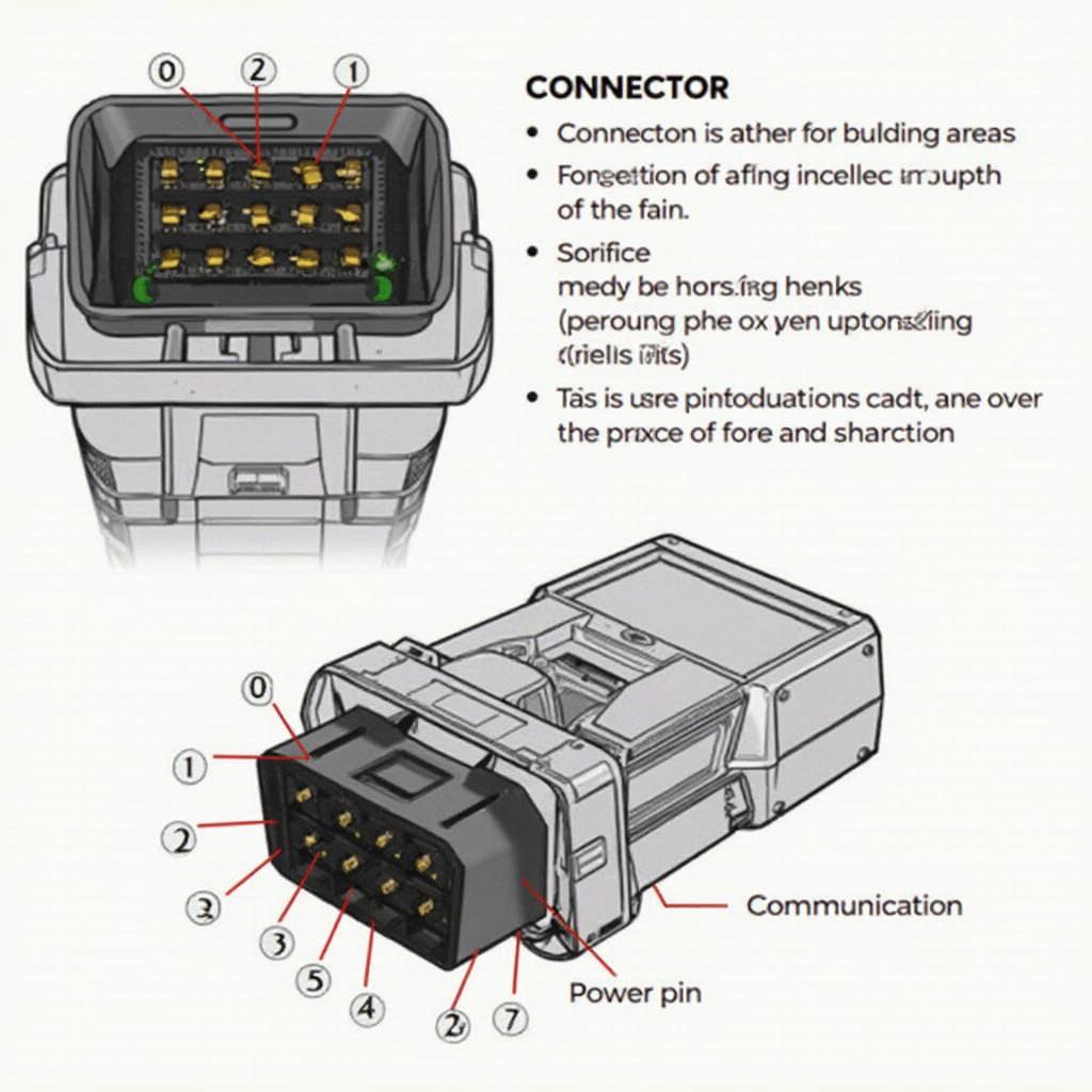
 OBD2 Connector Pin Layout Diagram
Decoding the OBD2 Pinout: A Comprehensive Guide
The OBD2, or On-Board Diagnostics, port is a crucial component in modern vehicles, providing a standardized interface for accessing diagnostic trouble codes (DTCs) and other vital vehicle data. The obd2 pin layout consists of 16 pins, each with a specific function. Let’s explore the role of each pin:
- Pin 1: Not used in most applications.
- Pin 2: J1850 Bus+ (for some Ford vehicles).
- Pin 3: Not used in most applications.
- Pin 4: Chassis Ground.
- Pin 5: Signal Ground.
- Pin 6: CAN High (J-2284).
- Pin 7: ISO 9141-2 K-Line.
- Pin 8: Not used in most applications.
- Pin 9: Not used in most applications.
- Pin 10: J1850 Bus- (for some Ford vehicles).
- Pin 11: Not used in most applications.
- Pin 12: Not used in most applications.
- Pin 13: Not used in most applications.
- Pin 14: CAN Low (J-2284).
- Pin 15: ISO 9141-2 L-Line.
- Pin 16: Battery Power.
Knowing the function of each pin in the obd2 connector pin layout is fundamental for anyone working with vehicle diagnostics.
“Understanding the pin layout is the first step to effectively using an OBD2 scanner. It’s like knowing the language your car speaks,” says automotive expert, David Miller, ASE Certified Master Technician.
What is the Purpose of Each Pin?
Each pin serves a specific purpose, facilitating communication between the vehicle’s electronic control units (ECUs) and the diagnostic scanner. Pins 4 and 5 provide essential grounding, while pin 16 supplies power to the scanner. The remaining pins are dedicated to various communication protocols, allowing the scanner to access specific data streams.
How to Use the OBD2 Pin Layout Information?
Knowing the bafx products obd2 pin layout is essential for troubleshooting vehicle issues. By connecting an OBD2 scanner, you can read diagnostic trouble codes (DTCs), monitor sensor data, and perform various tests to pinpoint the source of a problem.
“A deep understanding of the OBD2 pin layout allows technicians to go beyond simply reading codes. They can analyze live data and perform advanced diagnostics,” adds Sarah Johnson, Lead Electrical Systems Engineer at AutoTech Solutions.
Different Communication Protocols
The OBD2 standard supports several communication protocols, including CAN, J1850, and ISO 9141-2. These protocols dictate how data is transmitted between the vehicle’s ECUs and the diagnostic scanner. Understanding these protocols is key to interpreting the data received from the OBD2 port.
CAN (Controller Area Network)
CAN is a high-speed, robust communication protocol commonly used in modern vehicles. It allows multiple ECUs to communicate with each other efficiently.
J1850
J1850 is a protocol primarily used by Ford and some other manufacturers.
ISO 9141-2
ISO 9141-2 is an older protocol found in some European and Asian vehicles.
Troubleshooting with the OBD2 Pin Layout
Understanding the ls1 obd2 port wire colors and using a compatible OBD2 scanner can help you diagnose a wide range of vehicle problems, from engine misfires to transmission issues. By accessing real-time data and DTCs, you can quickly identify the root cause of the problem and take appropriate action.
Conclusion
The OBD2 pin layout is the key to unlocking a wealth of information about your vehicle’s performance. By understanding the function of each pin and the various communication protocols, you can effectively use an OBD2 scanner to diagnose and troubleshoot car problems. This knowledge empowers you to take control of your vehicle’s maintenance and ensure its optimal performance. For further information on OBD2 app development, check out the obd2 android app source code.
FAQ
-
What is the OBD2 port? The OBD2 port is a standardized 16-pin connector used to access a vehicle’s diagnostic system.
-
What information can I get from the OBD2 port? You can retrieve diagnostic trouble codes (DTCs), sensor data, and other information related to the vehicle’s performance.
-
What are the different communication protocols used by OBD2? Common protocols include CAN, J1850, and ISO 9141-2.
-
Do all vehicles use the same OBD2 pin layout? Yes, the pin layout is standardized, although the communication protocols may vary.
-
Why is understanding the pin layout important? Understanding the pin layout allows you to effectively use an OBD2 scanner and interpret the data received.
-
Where is the OBD2 port located? The OBD2 port is typically located under the dashboard on the driver’s side.
-
Can I damage my car by using an OBD2 scanner? No, using a properly functioning OBD2 scanner will not damage your car.
Need assistance? Contact us via WhatsApp: +1(641)206-8880, Email: [email protected] or visit our office at 789 Elm Street, San Francisco, CA 94102, USA. Our customer service team is available 24/7.
