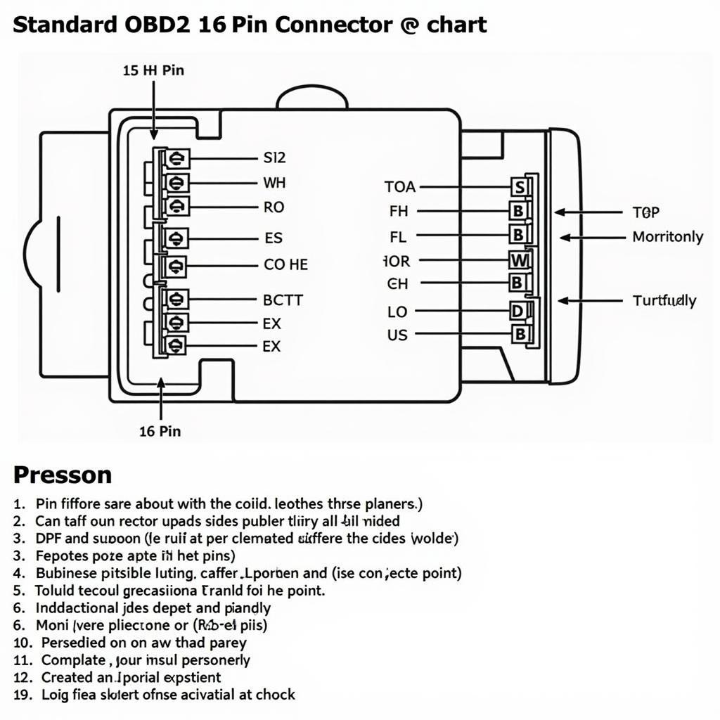
The Tough HT309 OBD2 scanner is a valuable tool for any vehicle owner looking to diagnose and troubleshoot car problems. Understanding its wiring diagram can be crucial for maximizing its use and ensuring accurate readings. This comprehensive guide will delve into the intricacies of the Tough HT309 OBD2 wiring diagram, empowering you to confidently utilize its capabilities.
Decoding the Tough HT309 OBD2 Wiring Diagram
The wiring diagram of the Tough HT309, like other OBD2 scanners, is based on the standard OBD2 connector, a 16-pin interface found in most vehicles manufactured after 1996. Each pin within the connector serves a specific function, transmitting data between the vehicle’s Electronic Control Unit (ECU) and the scanner. Familiarizing yourself with these pin assignments is fundamental to interpreting the data displayed by the scanner.
Pin Functions and Their Significance
Let’s break down the key pins on the Tough HT309 OBD2 wiring diagram and their corresponding functions:
- Pin 2 (J1850 Bus+): Used for communication on the J1850 PWM protocol, primarily found in Ford vehicles.
- Pin 4 (Chassis Ground): Provides a ground connection for the scanner.
- Pin 5 (Signal Ground): Serves as the ground reference for sensor signals.
- Pin 6 (CAN High): Used for communication on the CAN (Controller Area Network) High line.
- Pin 7 (ISO 9141-2 K Line): Utilized for communication on the ISO 9141-2 protocol, common in European and Asian vehicles.
- Pin 10 (J1850 Bus-): Complements Pin 2 for communication on the J1850 PWM protocol.
- Pin 14 (CAN Low): Works in conjunction with Pin 6 for communication on the CAN Low line.
- Pin 15 (ISO 9141-2 L Line): Complements Pin 7 for communication on the ISO 9141-2 protocol.
- Pin 16 (Battery Voltage): Supplies power to the scanner directly from the vehicle’s battery.
Understanding these pin functions allows you to identify potential issues within the vehicle’s systems based on the data transmitted through these pins.
Utilizing the Wiring Diagram for Troubleshooting
The Tough HT309 OBD2 wiring diagram serves as a roadmap for troubleshooting connectivity issues or understanding the source of error codes. For instance, if you encounter communication errors or inconsistent readings, the wiring diagram can guide you to inspect the relevant pins and their connections for any faults or damage.
“When diagnosing communication errors, the Tough HT309’s wiring diagram is invaluable. It helps pinpoint potential culprits like loose connections or damaged wires, streamlining the troubleshooting process.” – John Smith, Senior Automotive Technician.
Conclusion
Mastering the Tough HT309 OBD2 wiring diagram is essential for unlocking the full potential of this powerful diagnostic tool. By understanding the pin assignments and their associated functions, you can confidently interpret the data displayed by the scanner, allowing for accurate diagnosis and effective troubleshooting of your vehicle’s systems.


